It seems like a bare-essentials natural: a Pierce "aperiodic" oscillator driving a non-neutralized power amplifier for a multiband Morse code transmitter that requires just one coil and minimum adjustment. This page explores that topology, the Boosted Pierce (Figure 1), from its Great Depression beginnings through its canonization as a ubiquitous "glowbug" design that just won't go away. Fundamental to understanding the circuit is that it's an aperiodic-anode tri-tet oscillator that uses separate triode and screen-grid (tetrode or pentode) tubes.
|
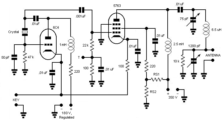
| Figure 1 — Boosted Pierce transmitter based on the version described by Don Mix, W1TS, in October 1968 CE QST. Some variations use more or less voltage, regulated or not, on the oscillator; some variations include a cathode bias resistor in the final amplifier and some don't; some key both stages and some key only the final amplifier; this version uses a voltage divider to supply final screen voltage rather than the series resistor used in many versions. All have the same aim: better performance than an oscillator-only transmitter without the fuss and bother of neutralization—but it turns out that neutralization is well worthwhile for multiple reasons. Test point T allows measurement of the final grid current, with every 0.1 V across the associated 100-ohm resistor equating to 1 mA of grid current in the 5763—a value worth measuring, because underdrive is likely at 7 MHz and higher frequencies in every Boosted Pierce design that does not overstress its crystal. RS1 and RS2 are proportioned to set the screen voltage to 204 V, key down, in my test version. (Schematic symbols [Tubepad] and original Mix "Novice Special" Boosted Pierce transmitter schematic by Gary Johanson, WD4NKA) |
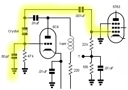 |
| Figure 2 — Why the Boosted Pierce can produce output with its oscillator tube removed or disabled: The crystal is connected between the amplifier grid and ground through the oscillator's grid feedback capacitance (in this case, 50 pF) and (if the oscillator tube is disabled but left in its socket and its cathode is bypassed to common for RF, as it is here) the oscillator tube's grid-to-cathode capacitance (around 10 pF). |
Multiple writers noted this effect. The Bliley Electric Engineering Bulletin E-6 warned that crystal fracture may result:
...excessive excitation will fracture a quartz crystal rendering it useless. The following are the outstanding sources of excessive excitation: .... (11) in certain instances, by removing the plate voltage from a Pierce Oscillator employing an untuned tank. This is a unique situation in that the buffer stage, which follows the oscillator, can act as a crystal controlled oscillator. The crystal is effectively connected between the control grid and ground of the buffer tube and, if the buffer plate tank is tuned to the crystal, that stage can act as a crystal oscillator when the voltage is removed from the oscillator stage proper. If conditions in the buffer stage are incorrect for a crystal oscillator, the crystal may be fractured.
November 1937 CE: Radio Describes a Transmitter Based on the Pierce Oscillator
In "Airline Transmitter Adaptable for Amateur Use" (Radio, November 1937 CE, pages 32–38 and 81), G. E. Smith, W4AEO, described a commercial transmitter design based on a 42 pentode Pierce oscillator:
This oscillator, with crystal between control grid and plate, is commonly called the Pierce Circuit. If a coil-condenser tank is substituted in place of the crystal, it will be seen at once that it becomes similar to an ultra-audion or Colpitts circuit.
This circuit was selected after all types of crystal oscillators had been tested, complete sets of readings had been tabulated, and the advantages and disadvantages of each taken into consideration. Each type of oscillator was keyed by various methods and the shape of the keying was checked on the oscilloscope.
The only disadvantage of the Pierce oscillator is low output as compared with the more common oscillators, pentode, tri-tet, 6L6, et. But a crystal oscillator should not be used for power output, as it has one primary function and that is to control the frequency of a transmitter. The r.f. crystal current should be kept low at all times to minimize frequency drift. Why make the crystal do all the work when, by the addition of another small inexpensive tube, the crystal can be run at low output and the burden shifted to the second tube? An ordinary receiving tube is much cheaper than a crystal. Through the use of the Pierce circuit no more tanks are required; in fact, one less tank is used in this circuit that is used in a tri-tet. The output from the two arrangements will be about the same. Another advantage of the Pierce is that the plate circuit is untuned and there are consequently no critical tuning adjustments which must be made for proper keying.
This oscillator is by far the most active of any circuit that was tried. To prove this during the preliminary tests, some very poor grade of X-cut crystals that refused to oscillate in other circuits, including the tri-tet, all oscillated actively when put in the Pierce oscillator; it was even possible to key these heretofore inactive crystals at high speeds.
* * *
Should this circuit be tried for amateur use, it is suggested that an octal socket be used which would allow the use of a 6F6G, 6V6G, or 6L6G without any circuit change. All have been tried with excellent results, especially the 6L6G.
January 1938 CE: Jones's 6C5–807 160-Meter 'Phone
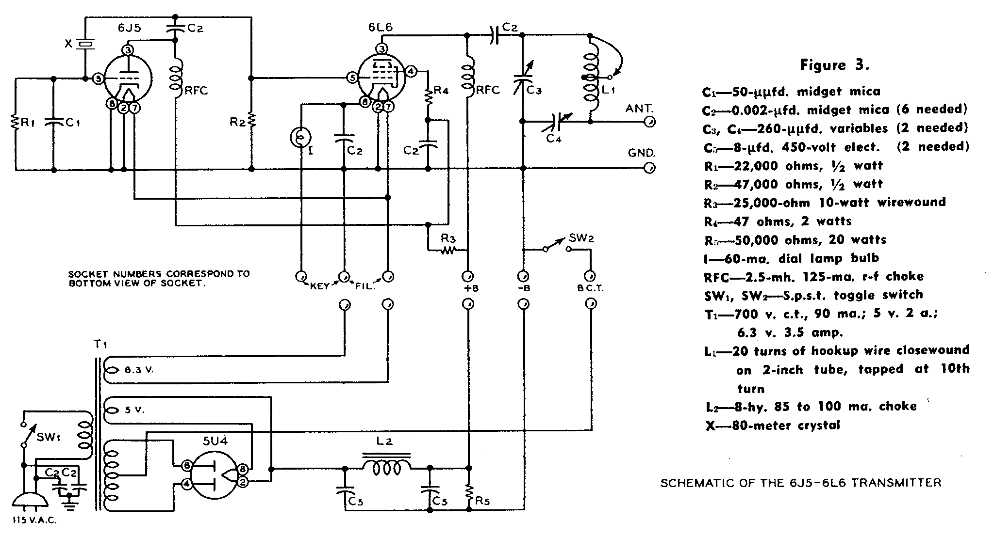
This circuit (Figure 3) is the first publication of the triode-pentode Boosted Pierce transmitter—that is, a Pierce oscillator that drives a non-neutralized amplifier feeding an antenna. So Frank Jones can be considered to be the inventor of the Boosted Pierce—until we take a closer look at the January 1938 issue of Radio in which the circuit appears.
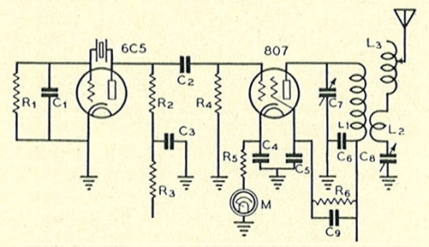 |
| Figure 3 — Frank Jones's 160-meter (and 75-meter) phone transmitter from pages 130–134 of the January 1938 edition of Radio. This is the first appearance in print of the triode-pentode Boosted Pierce; that same year, the Radio Handbook would name it. |
For the first few years after the 807 was introduced, its original manufacturer (RCA) recommended operating the tube at no more than 400 to 500 V (officially upped to 750 V later) and that cathode bias from a resistance on the order of 400 ohms be used in addition to any additional bias provided by a grid-leak resistor and/or a negative dc supply. As a result, the power-amplifier design in this very first Boosted Pierce implementation in effect includes Class A bias—not to protect against the underdrive later to become endemic in Boosted Pierce designs operating at higher frequencies, but rather in accordance with RCA's recommendations for proper application of the 807. (Since writing the previous sentence, I have also begun to suspect that RCA's recommendation that Class A bias be included in ostensibly Class C stages may have been intended to stave off the dynatronic instability declared by RCA beam-tube-designer Otto Schade to be likely under just the voltage and current conditions Class C operation entails.) At the higher operating frequencies covered by later implementations of the Boosted Pierce, shunt capacitance in the oscillator-plate-to-final-grid circuit, and increased feedback/feedthrough caused by the final's unneutralized grid-plate capacitance, would reduce the driving power at the final grid to less than that necessary for true Class C operation. Many of these implementations nonetheless omit final-amplifier cathode biasing, resulting, in many cases, in underbias that causes excessive plate dissipation in the final—a condition commonly overlooked because measuring output power was relatively problematic for hobbyists, and because the FCC regulations of the day required that transmitter power be evaluated merely in terms of power input.
September 1938 CE: The Norfolk Radio Amateurs Prepare for Emergency with the Boosted Pierce
December 1938 CE: Goodman's 6C5– 6L6 Transmitter
1938 CE: The Fifth Edition of the Radio Handbook Names the Boosted Pierce
Four of the seven "Multi-Tube Exciters" described in the "Exciter Construction" chapter of the October 1938 CE Radio Handbook use Pierce oscillators: three based on Frank Jones's harmonic Pierce "regenerative" oscillator—which, as in its original description in Radio, he studiously avoids describing as a Pierce circuit—and two based on the classic triode Pierce. The first circuit in the section, "Two-Tube, Two-Band Exciter with Single Tank Circuit," coins the name I use for the circuit in the terse caption for its schematic (Figure 3): "Wiring diagram of the 'Boosted Pierce.'" (note the quotation marks; that was the Radio crew's name for it, too.) Its principal attraction and its principal oddity are described in the same sentence: "No neutralization is needed for working on the same frequency as the crystal; the 6L6G sort of 'takes over' and acts somewhat as a regular 6L6G crystal oscillator."
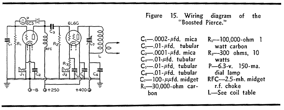 |
| Figure 3 — A write-up in the fifth edition of the Radio Handbook (1938 CE) gave the Boosted Pierce its name. Coil data was supplied for 160 through 10 meters; "the output will vary from 3 to 15 watts, depending on the frequency of the crystal and supply voltages....With 10-, 20- and some 40-meter crystals, the coupling must not be too tight, loading the 6L6G too heavily, or the crystal may act sluggish or refuse to oscillate." Considering that most variations on the Boosted Pierce do not drive their power amplifiers hard enough to develop class C bias, the inclusion of a cathode-bias resistor for the 6L6G is a good thing. |
1939 CE: Boosted Pierce Portable-Emergency Transmitters in the 1940 ARRL Radio Amateur's Handbook
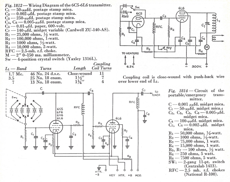 |
| Figure 4 — Two Boosted Pierce schematics appeared as Figures 1812 and 1814 of the "Emergency and Portable" chapter of the 1940 ARRL Radio Amateur's Handbook. One (Figure 1812) is Goodman's 6C5–6L6 circuit from December 1938 QST (from its skewed appearance—largely corrected here—the actual schematic cut used in printing QST); the other (Figure 1814), part of a modular portable-emergency station, is complete down to the practically necessary nuances of cathode-bias resistors for oscillator and final, and grid and screen parasitic-oscillation stoppers in its 6L6 final. |
1941 CE: Hadlock's Portable-Emergency Transmitter
Might we overcome the Boosted Pierce's tendency toward amplifier underdrive and crystal overdrive on higher-frequency bands by using a screen-grid oscillator tube in front of a triode? The National Company's Calvin Hadlock, W1CTW, described just such a circuit in July 1941 CE QST's "A Versatile Portable-Emergency Transmitter", the schematic for which is shown in Figure 5.
 |
| Figure 5 — Schematic of Hadlock's two-beam-tube Boosted Pierce transmitter. Screen-grid keying the power amplifier allows the use of 7AC/7S-based metal tubes (6V6, 6L6, 1631, 6F6) or 1Q5 battery tubes. |
A test version of the Hadlock Boosted Pierce I built—consisting of a 12V6GT tetrode-connection Pierce oscillator (213 V plate and 105 V screen, both regulated, with 470 ohms of cathode resistance and 51 pF of additional grid-to-ground feedback capacitance) driving a shielded 6417 (12-V 5763) beam tube (360 V plate, key down; 267 V screen [from 18-kilohm series dropping resistor], key down, 22 kilohm grid leak with no series choke, 340 ohms of cathode resistance)—produced 7.5 to 7.7 W at 80 meters, 5.3 to 6.0 W at 40 meters doubling from an 80-meter crystal, and 4.7 W at 40 meters using a 7.01-MHz crystal. The 6417 grid current was 3.2 mA with my 3.57-MHz crystal and 2.51 mA with my 7.01-MHz crystal, indicating sufficient drive for class C. With the 3.57-MHz crystal, short-circuiting the final's cathode resistance increased grid current to 3.58 mA and increased output to 8.18 W. Simultaneous cathode keying of the oscillator and amplifier was used.
Unlike many other Boosted Pierce implementations, Hadlock's circuit—at least when other than 1Q5 tubes are used—drives its final sufficiently hard for class C operation. In every configuration, however—straight through on 80, doubling to 40, straight through on 40—there was moderate, long-term yoop, indicating considerable crystal heating that must be considered dangerous. (And the crystals I used were pre-FT-243 crystals—mainly FT-171B units intended for use in the Hallicrafters HT-4/BC-610 transmitter.) Hadlock's keying method of letting the oscillator run while making and breaking the final screen supply would largely mask this effect, but the thermal-cycling stress on the crystal would still occur, if less often. Because of this, and especially considering that modern crystals can tolerate even less drive that the relatively large crystals of the 1930s and 1940s, I can recommend the Hadlock Boosted Pierce only in its lower-power, 1Q5GT-based form—pending investigation of the crystal stress in that configuration.
An eye-opening find: The plate, grid, cathode, metal shell, and heater connections are the same for 7AC-based beam power tubes as for 6C5 and 6J5 triodes. This allows us to freely substitute 6C5/6J5s for the 6V6 in the circuit's oscillator stage with no wiring changes. On trying this, I discovered that using a metal 6C5 or 6J5 instead of a metal 6V6 drove the power amplifier to the same or slightly more output than the 6V6!
Both transmitter designs in the "Simple Transmitters" chapter of the Radio Society of Great Britain's November 1949 Simple Transmitting Equipment booklet are based on Hadlock's two-screen-grid-tubes Boosted Pierce design. The writeup of the first one, "Simple, Two-Valve Transmitter for 1.8, 3.5 and 7 Mc/s Operation," directly confirms my finding of dangerously high crystal current through this caution:
The crystal circuit chosen (a Pierce oscillator) has the advantage of being extremely simple, since it requires no tuned circuits to make it oscillate. It has one disadvantage, however, in that the R.F. current flowing through the crystal is inclined to be rather high, and unless care is taken in the design of the circuit a fracture of the crystal might result. In this transmitter the crystal current has been reduced to a minimum by careful choice of component values and the use of high-efficiency valves [both stages use the QV04/7, a beam power tube similar to a glass 6V6—W9VES]. Crystals with 7 Mc/s fundamental frequencies have proved quite successful, but when purchasing them it should be stated that they are for use in a Pierce oscillator circuit. This point is most important. [emphasis in original]
From Bliley Electric Engineering Bulletin E-6:
If a transmitter is to be built on the basis of published constructional information, the crystal oscillator portion should be carefully checked with respect to the crystal frequencies intended to be used. This precaution is advisable in view of the fact that some circuits, designed on the basis of certain oscillator frequencies, are not satisfactory for crystals at higher frequencies. For instance, a certain oscillator which functions well with 80-meter amateur crystals, can have characteristics such as to cause fracturing of 40-meter crystals due to excessive feedback at the higher frequencies. Particular attention, in this respect, should be paid to Pierce and modified-Pierce oscillators.
1946 CE: The QST Longfeller
1947 CE: The Eleventh Edition Radio Handbook's Longfeller "Me-Too"
Like its predecessor in 1946 CE QST, the Radio Handbook's postwar Boosted Pierce (Figure 6) promoted low-cost wood construction.
 |
| Figure 6 — Boosted Pierce transmitter schematic from pages 287 and 288 of the 1947 CE (11th edition) Radio Handbook. Significantly, this design, the power amplifier of which lacks protective cathode bias but includes a 47-ohm resistor between its screen and screen bypass capacitor to stop intrinsic-negative-resistance-caused parasitic oscillations, is intended to produce 3.5- and 7-MHz output using 3.5-MHz crystals only—that is, to develop 40-meter output by doubling from 80. Only the power amplifier is keyed. "The transmitter will deliver between 10 and 15 watts to the antenna on the 80-meter band and 5 to 8 watts on the 40-meter band with the same crystal and coil being used on both bands." Half of the power amplifier coil's 20 turns are shorted out for 40-meter operation, roughly halving its inductance. |
1951 CE: W2FZW's 6C4-2E26 "Novice Special"
As it was originally instituted in July 1951, the US Novice class license granted high-frequency privileges only from 3700 to 3750 kHz. "The Novice Special," an 80-meters-only Boosted Pierce design published on pages 11–15 and 54 of July 1951 CE CQ by S. G. Reque, W2FZW, sought to make life easier for Novice newcomers through set-and-forget transmitter tuning. Figure 7 shows its schematic and parts list.
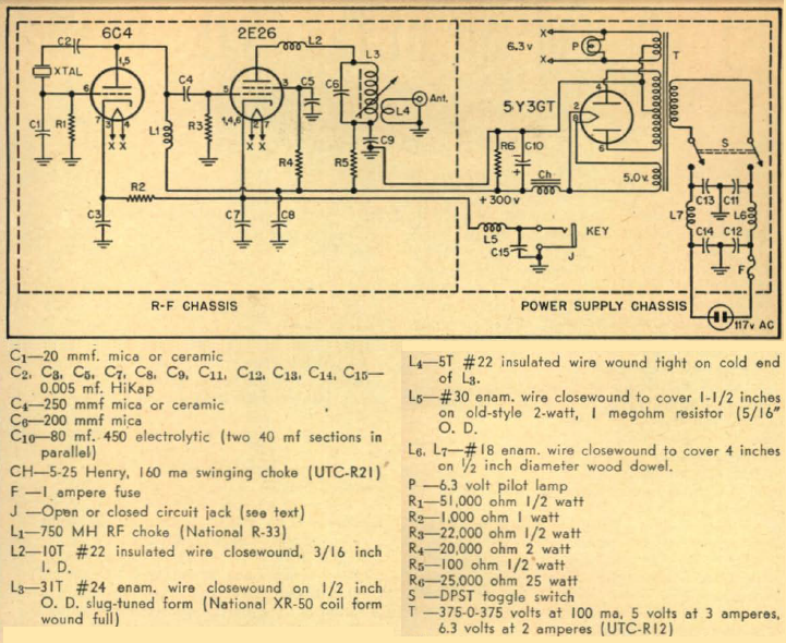 |
| Figure 7 — S. G. Reque's "Novice Special" from page 15 of March 1951 CQ magazine. Unusual in this design is the absence of front-panel amplifier-output adjustments: "The 80-Meter Novice Rig may . . . be operated in any portion of the 3700 to 3750 kc. band without further tuning." (The use of a 2E26 transmitting tube at an input power level easily handlable by a beam power receiving tube also attracts our attention and is explored in the text.) The inductance of the final-amplifier output coil, L3, works out to 8.82 μH for resonance at 3725 kHz with 207 pF (the capacitance of C6 [200 pF] plus the 2E26 output capacitance [7 pF]). |
Considering the rig's "Novice Special" monicker, it's a bit odd to find this passage soon after the article begins:
In addition to serving as a c-w transmitter, this rig has been designed so that the final is capable of 100% amplitude modulation. In this sense the 80-Meter Novice Special will be useful long after its owner has progressed to higher-class licenses, because the rig may serve as a mobile, standby or emergency transmitter.
Outright hard to defend is the use of a 2E26 transmitting tube when a less-expensive 6AQ5 or 6V6 audio beam power tube would have provided the same output at the design's stated final-amplifier-plate input power (nominally 15 watts [50 mA at "280 to 320 V"]). It's the sort of thing we might attribute to a strapped-for-cash magazine staff's use of free lab stock provided by a tube manufacturer—if, as with ARRL's QST, the magazine staff actually had a lab, which CQ didn't. But the author's "Schenectady 8, New York," address ("1250 Garner Avenue" with no further qualification), provides a clue: Might he have been associated with a Schenectady-based company that, among other things, manufactured tubes?
Sure enough, a half hour's worth of Internet searching ultimately provides us with the November-December 1957 CE issue of G-E Ham News, on page 7 of which we
MEET THE DESIGNER—W2FZW/7 (now officially K7BGI), S. G. (Ty) Reque, shows herein that you can teach an old oscillator new tricks. Of course, Ty is an expert at this, having designed several of the most popular gadgets that have ever appeared in G-E HAM NEWS. These include the original Economy Half Kilowatt, Interpolating Frequency Standard, Emergency-Portable Rig, Mobile Modulator, TVR Hi-pass Filter, Mobile/Portable Power Supply, the Field Meter, and several "Technical Tidbits" items. Formerly associated with G.E.'s General Engineering Laboratory, Ty now counsels the new G-E Computer Department, in Phoenix, Arizona, as an engineering consultant. His professional background also includes stints with the General Electric Research Laboratory, and the then Transmitter and Tube Divisions . . . .
Flogging an unnecessarily expensive, specialized part to newcomers who don't know better and hiding an author's related professional affiliation? Shame on you, CQ.
1957 CE: W3RMG's 90-W-input 6AU6–6146 Boosted Pierce
1968 CE: Mix's 6C4–5763 "Beginner & Novice" Transmitter
In March 2008 CE, peripheral to new experiments with the Caringella 5763 transmitter, I briefly tested the Mix 6C4–5763 Boosted Pierce circuit at 7 MHz under these conditions:
6C4 (oscillator) plate voltage: 180, regulated
5763 (amplifier) plate voltage: (key down): 360
5763 plate current: TBD
5763 screen voltage (key down): 204
5763 grid current: 1.6 mA
5763 plate pi net inductance: TBD
Output power: TBD
Efficiency of 5763 stage: TBD
The arrangement of the test circuit allowed me to key only the 5763 or the 6C4 and 5763 simultaneously. This was useful because the crystal environment created by the oscillating 6C4 stage resulted in considerable yoop (frequency shift across multiple Morse Code elements [dots, dashes]) at oscillator turn-on. Keying both stages simultaneously would cause this frequency shift to restart many times during a transmission, whereas turning on the 6C4 and keying only the 5763 amplifier stage would cause the yoop to happen only at the beginning of a transmission, allowing me to render it practically inaudible to other stations if I waited to start sending until after the oscillator had stabilized.
In practice, keying both stages resulted in considerable yoop that differed somewhat from the turning-on-only-the-oscillator yoop, likely because of feedback and load shift contributed by the 5763. Turning on the oscillator stage at the beginning of each transmission and keying only the amplifier stage gave yoopless keying, but with two artifacts: (a) because the amplifier stage was not neutralized, a neighborhood-audible backwave was present that I knew, from listening long ago to a mile-away friend's taped reception of my 1970s version, would be audible whenever the key-down signal was sufficiently strong, and (b) an FSK effect, audible if the backwave was audible, caused by shifting oscillator loading as the amplifier stage was keyed.
Although the on-air effect of oscillator-startup yoop can be minimized by turning the oscillator on and off only once per transmission, I consider yoop to be an indication of crystal heating that is potentially damaging to the crystal whenever, and however often, it occurs. But even with the oscillator stage producing 1.6 mA of grid drive, the unneutralized 5763 is not yet overdriven—increasing oscillator plate voltage above 180 increased the amplifier output, indicating that overdrive had not yet been reached—so reducing oscillator plate voltage below 180 would also reduce the transmitter's output power and efficiency.
Bottom line: At least at 7 MHz and higher frequencies—I have not yet tried the circuit at 3.5 or 1.8 MHz—the 6C4-5763 Boosted Pierce is a poor transmitter design that endangers its crystal and sacrifices signal quality for the purpose of avoiding the easily implementable best practices of (a) using a tetrode or pentode oscillator circuit that operates as a triode-tetrode, thereby isolating the crystal from feedback and load shift attributable to the amplifier, and (b) neutralizing the amplifier, making the stage easier to drive and practically eliminating backwave by canceling key-up leakage.
And yet we love it still.
Glowbug Variations: The "One-Tube" Triode-Pentode Boosted Pierce
2003 CE: Johnston Builds the Mix 6C4-5763 Boosted Pierce in QST
2008 CE: UU1CC's Neutralized Boosted Pierce
Seeking to reduce chirp in his lovingly built Straight Key Night M.O.P.A Transmitter at 30 meters, Andy Nechaevsky, UU1CC, added neutralization to a Boosted Pierce as shown in Figure 8.
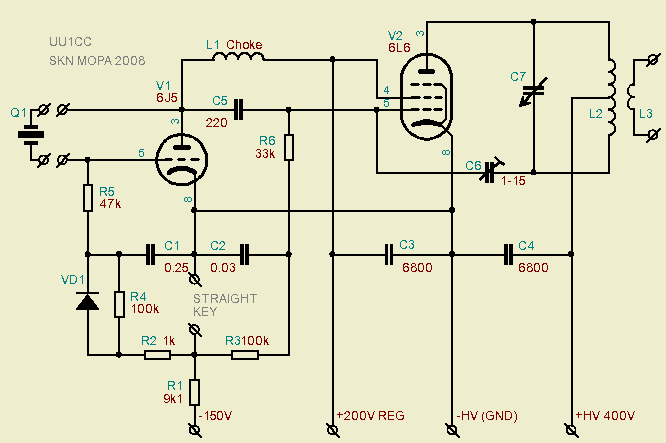 |
| Figure 8 — Andy, UU1CC, added neutralization (applied via C6 from balanced output circuit L2-C7) to his Boosted Pierce transmitter to eliminate chirp at 30 meters. The components in the cathode circuit of the oscillator (V1) form a differential-keying circuit in conjunction with a −150–V supply. |
In email communications of July 2011 CE, Andy answered several questions from me about his circuit:
> What's the performance difference with and without neutralization?

    First of all: in my case transmitter didn't work properly without
neutralisation at 30m - too unstable, low output and so on. It is possible
that my main problem - wooden chassis, I've never tried to use such design
before. Anyway, after the addition of neutralisation all troubles gone.

> Neutralizing a Boosted Pierce final is something I've considered for
> some time in the hope of cutting down reaction from final plate tuning
> and decreasing the RF level at the crystal.

    Yes, there was a big level of the RF signal on the crystal and the
neutralisation lowered it drastically. But, I have to denote again -
all my problems were on 30m band; the 40m and 80m version worked great
without any neutralisation.

    Hmmm... It is so interesting, but I've used a modern tiny crystal only on
30m - possibly that is the answer?
In a way cool later development for Christmas 2009 CE, Andy's Evergreen Exciter uses a 6BG6 in the final amplifier and a 6E5 Magic-Eye tube in the oscillator!
2013 CE: The W9VES Buffered Boosted Pierce
Minimizing the keying yoop that commonly occurs in Boosted Pierce transmitters—generally a result of crystal heating, especially noticeable at 7 MHz and above—is best done by turning on the oscillator at the beginning of each transmission and keying only the power amplifier. One drawback to doing this is backwave—leakage of the driving signal to the antenna through the grid-to-plate capacitance of the amplifier tube(s). Neutralizing the power amplifier, one approach to which is described above by Andy, UU1CC, minimizes backwave in addition to minimizing any yoop that occurs as a result of energy getting back to the crystal oscillator from the amplifier output.
In experiments with a well-neutralized Boosted Pierce, however, I was disappointed to find that yoop still occurred as I keyed the power amplifier with the oscillator running. Subject to proof or disproof through further experimentation, I consider its cause to be variation in the input capacitance of the power amplifier tube with keying and drive. The operating frequency of a Pierce oscillator is partially determined by the net capacitance across the crystal, after all, and the input capacitance of the amplifier tube(s)—in series with the coupling capacitance between the oscillator and power amplifier grid(s)—plays a role in setting that net capacitance.
What to do? With the amplifier neutralized, multiple oscillator topologies become feasible—including moving away from the Boosted Pierce idea altogether and resonating the amplifier grid circuit to achieve sufficient drive for class C operation. Nah, that's out; I wanted to solve this self-imposed problem within the self-imposed ham-dodge challenge presented by the Boosted Pierce with further ham-dodginess worthy of Boosted Pierce technology. Going to a modified Pierce oscillator could work—especially if I subjected the oscillator plate to overvoltage, as Richard Smith, W1FTX, did in his 6AG7–807 "A Beginner's CW Transmitter" in May 1948 CE QST—but I wanted to stay with a triode oscillator.
The answer proved to be simple: Add an untuned triode buffer stage between the transmitter's triode Pierce oscillator (originally a 12J5) and power amplifier (a 1631—a 12.6-V-heater metal 6L6). A 12SN7—two xJ5s in one envelope—would allow me to do the job without adding another socket. At first I built the buffer as a cathode follower, but its less-than-unity voltage gain (0.9 at theoretical best) proved disappointing, as maintaining every iota of drive is essential to the utility of the Boosted Pierce at 7 MHz and above. How about a common-cathode resistance-coupled stage? I'd be satisfied if in all of its capacitively shunted glory it would give enough gain to give at least 5 W out of the amplifier stage at 7 MHz.
And it does. With the 12SN7 and 1631 running safely within all of their respective current and dissipation ratings, the Buffered Boosted Pierce operates at a maximum of 5.4 watts output at 7 MHz and 9.5 watts output at 3.5 MHz with only the barest yoop detectable by ear (and only at beat notes lower than 150 Hz or so) at 7 MHz, and no yoop detectable by ear at 3.5 MHz, its backwave (estimated to be 2 mW) down 34 dB at 7 MHz and 36 dB at 3.5 MHz. It's a Boosted Pierce that doesn't sound like one.
2016 CE: The W9BRD 6JZ8 or 6AB4–6JQ6 Novice Rig Roundup Boosted Pierce
 |
| Figure 9—The Novice Rig Roundup Boosted Pierce transmitter currently covers only the 40-meter (7-MHz) amateur radio band. The enclosure is a Toy Story lunchbox; the tubes are a 6AB4 triode (Pierce oscillator) and 6JQ6 beam power tube (power amplifier), for both of which a 6JZ8 Compactron can be substituted. Plugging a tube-base-and-crystal-socket adapter into the 5-pin socket allows FT-243 crystals to be used. Power output is 7 watts with 246 V (key down) on the amplifier plate and 150 V regulated on the oscillator plate and amplifier screen. Amplifier-only keying is used to ensure a good-sounding signal; with the 6AB4 and 6JQ6 in use, the backwave (signal leakage through the final amplifier with the key up) is 34 dB down. The toggle switch (KEYING MODE/SPOT) turns on the oscillator for spotting and allows a choice of oscillator-amplifier or amplifier-only keying. (What's the Novice Rig Roundup? Glad you asked!) |
 |
| Figure 10—Schematic of the Novice Rig Roundup Boosted Pierce transmitter. All wiring of the KEYING MODE/SPOT switch is not shown. Keying waveshaping is done by means of a power MOSFET (IRF840 with gate-drive waveshaping) in an external keying/control box. Keying is better with the 6AB4/6JQ6 configuration, likely as a result of the greater isolation between amplifier and oscillator attributable the use of separate tubes. (Using a 6AB4 [half of a 12AT7] as oscillator results in much less oscillator-turn-on yoop than the 6C4 [half of a 12AU7] used in the now-classic Mix 6C4–5763 transmitter of October 1968 QST.) Careful amplifier tuning is required to get the best-sounding keying at 40 meters in either case. |
 |
| Figure 11—Wiring of the Novice Rig Roundup Boosted Pierce transmitter. Plenty of room is available for the later addition of switching and matching-network components for coverage of 80 and 160 meters. |
[to be continued...]
A Boosted Pierce Bibliography
Dana Bacon, W1CTW, "A Versatile Portable-Emergency Transmitter," QST, July 1941 CE.
Frank Jones, W6AJF, "A New, Simple 160-Meter Phone," Radio, January 1938 CE, pages 130–134.
Donald Mix, W1TS, "A Simple Transmitter for the Beginner," Beginner and Novice, QST, October 1968 CE, pages 22–28.
The Radio Amateur's Handbook, 17th/1940 edition (1939 CE, ARRL), pages 281–283 of the "Emergency and Portable" chapter.
The Radio Handbook, 11th edition (1947 CE), pages 287 and 288.
Roy Raguse, W6FKZ, "A Multiband Exciter with Instantaneous Frequency Switching," Radio, January 1938 CE, pages 32–34.
S. G. Reque, W2FZW, "The Novice Special," CQ, March 1951 CE, pages 11–15, 54.
C. Charles Tiemeyer, W3RMD, "A 3-Band, 90-Watt Transmitter," QST, March 1957 CE, pages 35–37.
| Revised July 1, 2016 CE. | Copyright © 2007–2016 by David Newkirk (david.newkirk@gmail.com). All rights reserved. |
| home |