QST's most recent development—the Tri-tet oscillator—has made the single-tube crystal transmitter a really practical affair at last. Practical because it is now possible to work equally well in two—and, in a pinch, in three—amateur bands with a single crystal. Unless we miss our bet, this particular set marks the beginning of the era in which the new amateur's first transmitter will be crystal controlled.—from the deck of George Grammer, "A One-Tube Crystal-Controlled Transmitter, QST, March 1934, pages 8–12, 88
The tri-tet (triode-tetrode, also commonly spelled tritet) oscillator circuit (Figure 1) was announced in James Lamb, W1CEI, "A More Stable Crystal Oscillator of High Harmonic Output," QST, June 1933, pages 30–32, as an improved means of generating radiofrequency (RF) power at harmonics (multiples) of the frequency of an oscillating piezoelectric frequency-control crystal. Misunderstood and misused, it went on to be reviled as a temperamental crystal destroyer. This page discusses the tri-tet's genesis, characteristics, and adjustment, and shows how the tri-tet, properly used, is nonetheless an excellent means of achieving good keying and high power output in a one-stage radio transmitter.
| |
|
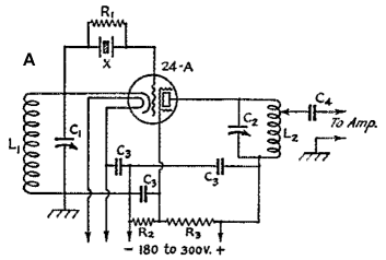
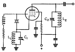
| Figure 1—(A) The Lamb tri-tet oscillator as diagrammed for transmitting use in the June 1933 QST magazine article that introduced it. (B) The Lamb tri-tet redrawn with its screen-grid tube portrayed a bit more modernly, and—to resistively load the crystal less, and to allow cathode-only keying (as opposed to B– keying) by breaking the dc connection between the cathode tuned circuit and common—with its grid-leak resistor decoupled by an RF choke and returned to common rather than to the tube cathode. The cathode tuned circuit, L1C1, is relatively high-C and is tuned to a frequency between the crystal fundamental and second harmonic—typically 5.9 MHz (3.3 μH in parallel with 220 pF) for a 3.5-MHz crystal. The output tuned circuit resonates at or near a crystal harmonic or—if a well-screened tube is used—near the crystal fundamental. The cathode tuned circuit, L1C1, must not be tuned near the crystal fundamental or destruction of the crystal may result; for this reason, C1 should not be variable in any modern, practical application of the tri-tet. | |
Talking Points
|
The tri-tet's genesis as an electron-coupled crystal oscillator. Electron-coupled oscillator basics and value (J. B. Dow, "Electron-Coupled Oscillator Circuits," QST, January 1932, pages 23–25; George Grammer, W1DF, "Electronic-Coupled Oscillators for the Small Transmitter," QST, October 1932, pages 13–17, 88. Jim Lamb's introduction of the tri-tet circuit in June 1933 QST ("A More Stable Crystal Oscillator with High Harmonic Output," pages 30–32)—but also a snippet from an early Hints and Kinks item (William P. Durkin, W2DHM, "Combined Oscillator and Doubler," For the Experimenter, QST, December 1932, pages 40–41 [see sidebar]) that (a) prefigured the tri-tet idea accurately by using a tuned-near-the-crystal-frequency tank circuit in the screen of a 47 power pentode or the second grid of a 46 dual-grid power tube with a second tank in the plate circuit tuned to a harmonic, and (b) Lamb did not explicitly credit in his introductory (and any later) article.
Multiple forms of the tri-tet. The underlying genius of the electron-coupled oscillator was the discovery that because the screen of a tetrode or pentode tube operates at a positive voltage relative to the tube's control grid and is electronically downstream from the control grid, the screen (more accurately called the accelerator grid in an audio power pentode or audio beam-power tube because its intended function is electron acceleration rather than electrostatic grid-plate shielding) can serve as an oscillator anode. This allows the plate of such a tube to be used to couple output from the cathode-grid-screen-triode oscillator through the tube's cathode-to-plate electron stream such that the plate plays (or may play, as in many implementations experimentation may reveal that the plate circuit provides more feedback than imagined) a relatively small role in providing feedback to start and sustain oscillation.
That early electron-coupled crystal oscillators included a tuned-circuit in the anode return of the cathode-grid-screen-triode oscillator and that Jim Lamb named his particular implementation of that approach tri-tet delayed more general understanding that every oscillator circuit that operates by means of an embedded cathode-grid-screen-triode oscillator is a tri-tet whether the oscillator anode is tuned or untuned (aperiodic). The classical Lamb tri-tet, and the Durkin tuned-screen oscillator that should rightfully be credited with having introduced the electron-coupled crystal oscillator to radio amateurs, are tuned-anode tri-tets. The later "grid-plate" circuit, the embedded oscillator in which is an aperiodic Colpitts arrangement, and the "modified Pierce" circuit, the embedded oscillator in which is an aperiodic Pierce arrangement, are untuned-anode or aperiodic-anode tri-tet oscillators. All are triode-tetrode oscillators in the sense that Lamb described for his particular implementation; all, therefore, are "tri-tets".
Early tri-tet implementations. Including the two-59s exciter from 1933 QST and the single-59 beginner's transmitter from 1934, but also bigger ones, like the RK-20/804 tri-tet so many hams suppressor-modulated for phone. This section introduces my theory that the Depression-era trick of bending one plate of the variable cathode-tuning capacitor so the capacitor would double as a switch between the tri-tet and tuned-plate, crystal-grid (TPXG) configurations, in conjunction with making the cathode tank tunable, was fundamental to the circuit's reputation as a crystal cracker. With this switching approach, all hams needed to do to endanger their crystals was, in changing from the TPXG configuration to tri-tet, forget to not key the oscillator as they unshorted/adjusted the cathode tuning capacitor. This mistake would bring up the oscillator with the cathode capacitance near maximum—with the cathode tuned close to, if not actually passing through, a dangerous-to-the-crystal-feedback point. Relatively soon, savvy designers would use a fixed capacitance to tune the cathode in conjunction with a switch to short-circuit the cathode tuned circuit for TPXG operation, in so doing disallowing the possibility of crystal destruction as a result of cathode mistuning. (Later in the evolution of this page I discovered the Bliley Electric Company's "Tinkering with the Tri-Tet" advertisement [below, reproduced from February 1947 QST], which confirmed my suspicion—with a graph of crystal current versus cathode-tank tuning—that this bent-capacitor-plate-as-tank-shorting-switch practice "takes the tuning through the danger zone.")
Evaluating the nonintuitive impedance versus frequency characteristic of the tuned-anode tri-tet anode (cathode or screen) tuned circuit. For a tuned-anode tri-tet with the anode tank connected in the cathode—the canonical Lamb tri-tet design—I recommend (for use with 3.5-MHz crystals) an anode tank consisting of 3.3 µH in parallel with 220 pF. Simulating its impedance with an RF circuit simulation computer program—in this case, Ansoft Designer SV 2—reveals why the tri-tet works better at harmonics than the fundamental for a given anode-tank tuning, and why tuning the anode tank to the crystal's fundamental resonance is dangerous to the crystal. At 3.5 MHz, the "3.3 µH in parallel with 220 pF" tank looks like a 6-µH inductor (reactance, 133 Ω); at 5.9 MHz (resonance), a 24-kΩ resistor; at 7 MHz, a 65-pF capacitor (reactance, 330 Ω).
What happens when we tune the cathode tank to the crystal fundamental? With 3.3 µH—a value after Chambers's oscillators article in March 1950 QST and not from the tri-tet's early days—we'd need a parallel capacitance of 609 pF to hit 3.55 MHz, the 80-meter frequency used in this discussion. At 3.55 MHz, the 3.3-µH inductor (Q, 200 at 5.9 MHz) in parallel with 609 pF looks like a 12.27-kΩ resistor.
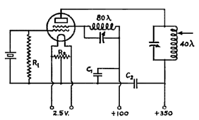
The variable oscillator-anode tuning used in early- and mid-1930s tri-tets—before it was generally understood that the oscillator anode tuning of a tuned-anode tri-tet could and should be fixed rather than variable—was generally lower-C and was commonly LC-proportioned such that it could be tuned to the crystal fundamental. Evaluating at 3.55, 5.9, and 7.11 MHz with our circuit simulator a widely-duplicated such circuit—the single-tube tri-tet-oscillator transmitter in George Grammer, W1DF, "A One-Tube Crystal-Control Transmitter," QST, March 1934, pages 8–12 and 88—we find that its cathode tank, for 7.11-MHz output with a 3.55-MHz crystal resonating at 5.363 MHz (based on a tank inductance of 11.74 µH with its 100-pF variable cathode-tuned-circuit capacitor set at "75% of full scale," looks like 21 µH (470 Ω) at 3.55 MHz, a 59.3-kΩ resistor at 5.363 MHz, and a 21-pF capacitor (690 Ω) at 7.11 MHz. At least for the 80-meter-crystal-doubling-to-40-meters case, this transmitter design helps its users avoid crystal danger by specifying a cathode-tank tuning capacitance maximum (100 pF) that's insufficient to allow the tank to be tuned to 3.5 MHz. These calculations assume a Q for the 11.74-µH inductor of 150 at 5.363 MHz.
The above description of tri-tet cathode-tuned-circuit impedance versus frequency omits the critical inclusion of the tube's cathode impedance acting in parallel with the tuned circuit. And what is that impedance? The basis for the answer of that question is that a first-order approximation of the cathode impedance of a vacuum tube (or the analogous element [emitter or source] in a transistor) is 1 divided by the device's grid-to-plate transconductance in siemens. Such is this relationship that the lower the device transconductance, the higher its cathode/emitter/source impedance.
Here the water muddies because of the dynamics of oscillation startup in conjunction with device physics. Because the transconductance of an oscillatory device that includes built-in automatic gain control—in a vacuum tube, resulting from grid-cathode rectification of the driving signal and resultant charging of the grid-to-common capacitance toward the negative peak of the driving signal—changes drastically from the "time zero" (key closure [grounding of the cathode for dc] in a cathode-keyed tube-based oscillator) to the "oscillating and output-amplitude-stabilized" states. The grid-plate transconductance of a 59 pentode is on the order of 2.3 millisiemens (mS; "2300 micromhos," as transconductance was represented long ago) when the tube is class-A biased per its published specifications. The cathode-to-common impedance of the tube in the class-A-biased state would therefore be 1 divided by 0.0023, or 435 ohms. If, when oscillating and output-amplitude-stabilized, that transconductance value dropped only by a factor of 4 as a result of self-AGC, its cathode impedance would increase to 1739 ohms (1 divided by 0.000575 S). But even if the circuit designer builds in a means of class A biasing—uncommon in the heyday of the original tri-tet—the actual swing in cathode impedance is much greater, because in Morse-code-operating practice the tube transitions from "key up"/"electronically off" (cathode impedance very high, a capacitive "open") to "key down"/"electronically on, oscillating, and output-amplitude-stabilized" (cathode impedance on the order of hundreds to several thousands of ohms). (The effective impedance of the tube grid also varies greatly across the non-conducting and conducting states.) The net result of this is that the crystal in a classical, tuned-cathode triode tri-tet is subject to wide, even wild, shifts in the impedance across its terminals as the oscillator circuit is keyed on and off. Resonating the cathode tuned circuit at the crystal fundamental maximizes this swing by placing a high pure resistance across whatever impedance the cathode exhibits, beginning with a high capacitive "open" with the tube OFF, to a resistive, relatively low impedance with the tube ON but before oscillation commences, to a resistance of hundreds to a few thousand ohms with the tube ON with oscillation having amplitude-stabilized by means of the tube's self-AGC.
Does the tri-tet's crystal shattering danger come from crystal overcurrent or overvoltage? The above exploration of tube cathode impedance swing and, by extension, crystal terminal impedance swing, as a classical tri-tet oscillator is on-off keyed in its cathode may be sufficient to explain why danger to the crystal rises as the cathode tuned circuit is tuned toward resonance with the crystal fundamental. But another factor may be in play, depending on whether only the tube's cathode connection to dc-common is keyed or the cathode connection to dc-common and the grid-resistor connection to dc-common are keyed together. [to be continued]
The tri-tet meets the beam power tube: 6L6 and other beam-power-tube-based tri-tets, and how Lamb's 1937 QST survey of crystal oscillators article overlooks an important design aspect by failing to take into account the effect of beam-plates-to-cathode hardwiring—that is, cathode-to-plate coupling—on stability and tuning issues in ungrounded-cathode oscillators that use such tubes.
Using the tri-tet at the crystal fundamental: The tri-tet was developed to reduce the number of tubes necessary to produce power at harmonics of the crystal fundamental. Amateur implementations of the tri-tet tended to use audio power pentodes (the 59 and 89) and, later, beam power tubes (the 6L6, 807, and 6V6) rather than well-screened transmitting pentodes such as the 804/RK-20 and 802. The poor screening and/or cathode-to-beam-plates-hardwiring of the former types commonly caused oscillation to cease when the tri-tet topology was used to develop output at the crystal fundamental. Because of this, and because through amateur radio tradition a crystal oscillator was considered to afford such a great frequency-stability gain over the LC-controlled oscillator that further improvement was rarely explored, the greater frequency stability made possible by the buffering action of the tri-tet configuration was only incidentally enjoyed during harmonic operation, and remained rarely encountered at the crystal fundamental until widespread use of the aperiodic-anode tri-tet ("'grid-plate' oscillator") topology.
A tri-tet shocker: Because the Lamb tuned-anode tri-tet puts the crystal between the grid and cathode, if we key both the cathode and the grid-leak ground return at the same time—and across various tri-tet schematics we sometimes see the grid leak across the crystal to cathode, or to ground (perhaps in series with an RFC)—we're doing B-minus keying, setting up a 50-50 chance that the round metal top plate of a big prewar crystal will be carrying the stage's full plate-voltage supply, at whatever current the tube will take when operating, relative to ground.
The 1941 ARRL Radio Amateur's Handbook Combination Oscillator Transmitter
The 1941 edition of the American Radio Relay League's The Radio Amateur's Handbook (available in Portable Document Format [PDF] form at http://www.tubebooks.org/) includes two single-tube-oscillator transmitters based on the 6L6 beam power tube: a tuned-plate, crystal-grid circuit, and a "combination" circuit (Figure 2) that can be switched between the "grid-plate" (aperiodic tri-tet) and tri-tet (tuned-anode tri-tet) configurations for straight-through and doubling operation, respectively, by plugging in an appropriately wired "cathode unit":
 |
| Figure 2—This combination transmitter circuit operates as an aperiodic tri-tet oscillator for output at the crystal fundamental frequency, and as a tuned-anode tri-tet for output at twice the crystal frequency. Capacitor C10, not present in the original circuit, is my addition; it allows adjustment of the oscillator output loading by series-resonating the output link. A pi or pi-L network can also be used for output coupling if high-pass filtering is added to suppress subharmonic (crystal fundamental frequency) output when the circuit is used as a frequency multiplier. |
The tri-tet meets the 6AG7—pre-World War 2. In a QST of autumn 1941, Goodman and Bubb publish a 5-meter mobile transmitter with a 6AG7-6AG7-6V6 lineup, introducing the first practical application in ham print of the excellent 6AG7 video amplifier pentode as a crystal oscillator—a tuned-anode tri-tet crystal oscillator that quadruples to 28 MHz for doubling by the second 6AG7.
Crystal maker Bliley helps hams tame the tri-tet: With postwar crystals generally smaller and more prone to fracture than their prewar equivalents, the Bliley Electric Company attempted to short-circuit tri-tet misadventures with a full-page "Tinkering with the Tri-Tet" advertisement on page 93 of February 1947 QST (Figure 3).
 |
| Figure 3—Bliley's full-page ad (February 1947 QST, page 93) is a tri-tet "how-to" in miniature. Many published tri-tet-based transmitter designs before and after violated the prohibition against using the tri-tet topology "straight through"—crystal and oscillator plate tuned circuit resonant in the same band—to the peril of crystal and keying quality alike. |
Hazardous tri-tet candy: Goodman's late-1940s beginner's tri-tet transmitter that had its plate coils wound on all-day-sucker sticks. Although this application of the tuned-anode tri-tet uses a fixed-tuned cathode circuit, it's really unfortunate in that (a) postwar crystals had much lower power-handling capability than prewar ones and (b) the tube's plate and screen operate at the same voltage (250 or more!), an arrangement that would have stressed even prewar crystals. I've seen multiple accounts of this circuit breaking crystals—and yet it was recently figured in QST, and a kit is currently available.
The tri-tet made more practical for modern crystals, but too late: Chambers's 1950 QST oscillator survey article shows very clearly via graphs and text how suppressor/beam-plates-tied-to-cathode tubes make poor electron-coupled crystal oscillators, including the tuned-anode tri-tet. This article confirmed and strengthened the role of the 6AG7 as a star crystal-oscillator performer for ham transmitters and officialized a short-term vogue (among ARRL HQ writers) for the 6AG7 modified Pierce as a best-you-can-build crystal-oscillator circuit. (And yet Smith, W1FTX, had earlier used a 6AG7 modified Pierce in May 1948 QST's "A Beginner's C.W. Transmitter" [pages 25–30; 420 V plate, 260 V screen on the 6AG7, key down!], and the 11th edition Radio Handbook [1947] had generally emphasized the value of the 6AG7 as a crystal oscillator tube.)
Later handbook coverage of the tri-tet: Even though the tuned-anode tri-tet had long been out of favor, ARRL and Radio Society of Great Britain handbooks of the 1950s and 1960s did a better job of explaining how it really worked, including how its "cathode" tank might as well have been, and could be, put in the screen circuit, with the cathode grounded, for essentially the same tuned-anode triode-tetrode function. (And so this echoes my finding that Durkin's original Experimenter's Section item in December 1932 QST, and not Lamb in 1933, had really introduced the tri-tet crystal oscillator; incidentally, we can see Durkin's idea implemented in a 1950s mobile transmitter from QST that used separate tuned-screen tri-tets on several bands.)
A modern dual-mode tri-tet: My version of the 1941 ARRL Handbook "Combination" oscillator is toggle-switchable between the aperiodic and tuned-anode tri-tet arrangements to get the best from a crystal at 80 (8 to 8.4 Wo at a screen voltage of 150 and plate voltage of 360, with a pi output network using a 13-µH solenoid) and 40, and exemplifies the 6JQ6/12JQ6/17JQ6 video-vertical-amplifier beam power tube as a crystal oscillator. I haven't experimented with LC ratio in the cathode tank and don't plan to; my rule of thumb, based on findings by Chambers in his 1950 article, for an 80-doubling-to-40 tuned-anode tri-tet is "3.3 µH in parallel with 220 pF." This tunes the tank to about 5.9 MHz, and works acceptably well.
[to be continued...]
| Revised August 16, 2014 CE. | Text not otherwise attributed is copyright © 2007–2014 by David Newkirk. All rights reserved. |
| home |