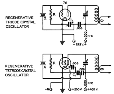
The April 1938 CE issue of Radio magazine (pages 47, 48, 75, and 76) published "A 'Sure-Fire' Crystal Oscillator" by Frank Jones, W6AJF—a "regenerative" oscillator that in its tetrode/pentode and triode forms (Figure 1) was described as capable of producing power output at harmonics of the crystal frequency. Cool! But all oscillators that operate by means of positive feedback are regenerative—so how does it really work?
|
| Figure 1—Jones's "regenerative" oscillators produce output at harmonics of the crystal frequency—an especially big deal for a triode oscillator, which we expect to be capable only of output at the crystal fundamental. |
Short answer: Operating in its frequency-multiplication mode, it's a Pierce crystal oscillator at its crystal's fundamental resonance and a locked ultra-audion LC oscillator at the harmonic output frequency, with harmonic output extracted through a link winding on the harmonic-tuned-circuit inductor. A re-rendering of the tetrode version for the June 1939 CE issue of Radio (and the 1939 CE and several subsequent editions of the Radio Handbook) helps us start to get the picture:
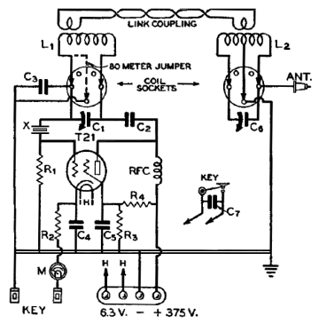 |
| Figure 2—The circuit looks much more Piercelike re-rendered for an exciter/beginner's transmitter described in the 1939 CE Radio Handbook. Configured for 3.5-MHz output, the circuit operates as a tuned-plate, crystal-grid tetrode oscillator. Comnfigured for 7 MHz output, it's a 3.5-MHz Pierce crystal oscillator that frequency-locks an LC ultra-audion oscillator operating at 7 MHz. (The ultra-audion tuned circuit consists of the series-tuned circuit formed by the crystal-holder capacitance in series with the inductive reactance of the parallel-tuned 7-MHz tank.) C3 operates only when the circuit is configured for 7-MHz operation, providing a ground return for the 7-MHz tank without stopping oscillation at 3.5 MHz. C3 also performs the critical task of adjusting the relative strengths of the 3.5- and 7-MHz oscillations to keep the frequency of the 7-MHz oscillation locked at twice the frequency of the 3.5-MHz oscillation. |
So, going forward, in this page and elsewhere, I'll refer to this general Jones oscillator topology with a term that conveys what it is: the harmonic Pierce.
On April 25 and 26, 2008 CE, I tested my version of the T-21 harmonic Pierce transmitter—with an actual, new-old-stock T-21—and measured these results with the circuit configured for second-harmonic-output at 7 MHz:
With plate voltage=360 and screen voltage=180: 3.4 watts output (Wo)
With plate voltage=360 and screen voltage=213: 4.9 Wo
With plate voltage=360 and screen voltage=255: 4.9–6.9 Wo
The plate inductor was a 9.4-µH solenoid (15 turns of #22 wire spacewound over 1-3/8 inches on a 1-15/16-inch-diameter form [a discarded ibuprofen bottle with its neck removed]), with a 3-turn link, series-tuned to ground with a 730-pF capacitor, for output coupling. Where a single output power is listed, the crystal was a 3.51-MHz FT-171 unit. Keying was yoopless with most crystals, and when yoop occurred it was slight—a significant achievement. (Also significantly in this connection, the 500-pF capacitor between ground and the crystal end of the tuned circuit consisted of two seriesed Radio Shack 0.001-µF discs—not a high-temperature-stability capacitance at all.) With FT-171 crystals, no frequency shift occurred as the output circuit was tuned through resonance at 7 MHz; a slight frequency shift occurred during plate tuning with a 3.525-MHz FT-243 crystal. The FT-243 crystal gave the most second-harmonic output. From this first look, the harmonic Pierce oscillator is a good choice for a single-tube-oscillator transmitter at 7 MHz.
Aside from testing the circuit's performance as a tuned-plate, crystal-grid tetrode oscillator at 3.5 MHz, I intend to evaluate the circuit's harmonic Pierce behavior with the 1631 (12-V metal 6L6), 6L6G, and several television horizontal-sweep-amplifier tube types. For it seems to me that one superficially puzzling aspect of the Radio harmonic Pierce beginner's transmitter is its use of a special-purpose transmitting tube, the Taylor T-21, when the T-21's mass-market prototype, the 6L6G, would have been cheaper and much more readily available. The T-21, says the writeup of the transmitter in June 1939 CE Radio, "is capable of taking more abuse than the 6L6G, and is therefore recommended"—and yet many Radio articles before and later pushed the 6L6G and other tubes well beyond their manufacturer-suggested ratings. The possibility aside that Radio was plugging the T-21 in exchange for free or reduced-price lab stock, one possibly significant difference between the two tubes for oscillator service is that the T-21's grid-plate capacitance is higher by one third—1.2 pF compared to the 6L6G's 0.9 pF.
[to be continued...]
| Revised February 1, 02020 CE. | Text copyright © 2008–2010 by David Newkirk. All rights reserved. |
| home |