Insufficient minimum potentials are indicated at highly negative grid voltages by the presence of secondary-emission effects but they have no harmful consequences inasmuch as this section of the plate characteristic is not utilized in practical operating conditions.—O. H. Schade, "Beam Power Tubes," Publication ST-59 (RCA: Harrison, New Jersey, March 01938 CE), pages 168–169.
A condition is frequently encountered in practice when an 807 will appear perfectly stable when running loaded with uninterrupted excitation and without modulation and yet will develop widespread clicks when the transmitter is keyed, or splatter when the amplifier is modulated. We have seen more than one commercial installation with heavy loading resistors across the tanks and they weren't put there to increase tank-circuit efficiency!—Don Mix, W1TS, "Amplifier Instability in Transmitters," QST, June 01948 CE, pages 19–24 and 110.
Is it any wonder that interference resulted?—W. E. Babcock, "Circuit Troubles Caused by Unusual Tube Effects," Electron Tube Design, RCA, 01962 CE
Electronic amplifier circuits sometimes unwantedly act as signal generators—oscillators—instead of merely amplifying. Since the dawn of the electronics era and the widespread use of vacuum tubes, such unintended oscillation has been called parasitic oscillation, a given case of such sometimes being called just parasitics. In many cases, parasitic oscillation occurs as a result of incomplete circuit design and/or insufficient attention given to details of real-world circuit construction. This page discusses the mechanism and cure of a particular class of parasitic oscillations that occur not because of poor circuit design or builder error, but rather as a result of the physics of a particular class of vacuum tube, early on referred to as the kinkless tetrode and later as the beam power tube—screen-grid tetrodes designed to exhibit pentodelike characteristics. Occurrences of this particular class of parasitic oscillation became commonplace as radio techologists went to work with the 807, a repurposed-for-RF audio tube later supplanted and expanded on by RF-service-intended beam-power-tube designs.
Significant negative-resistance effects endemic to first-generation beam-power-tube topology can set up conditions of one-port oscillation readiness that are neither explained nor predicted by such two-port characteristics as transconductance and feedback capacitance. Recognizing the beam power tube's tendencies for harboring one-port, negative-resistance oscillations allows us to intelligently apply stabilization measures that give acceptable practical stability without resorting to the ill-understood, hit-and-miss procedures described in decades of amateur and professional literature.
Negative Resistance and the Dynatron
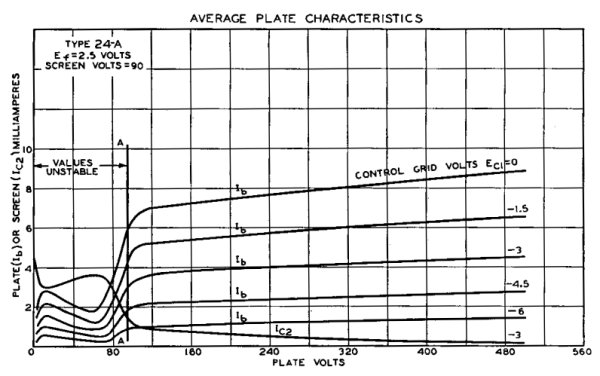
Negative resistance in tetrodes: The eye-opening characteristic curves of the early Type 24 tetrode (Figure 1) reflect a region of negative resistance that radio technologists put to work in the oscillator topology known as the dynatron. Manufacturers soon reduced the 24's ability to act as a negative resistor by treating the surface of its plate structure to reduce secondary emission.
|
| Figure 1—Plate-characteristics graph for the Type 24A tetrode, with negative-resistance region labeled as "Values Unstable." |
If a pair of phones is connected in series with the plate of the dynatron, it will oscillate at a high audio frequency. This frequency may be lowered to three cycles per second simply by increasing the inductance of the circuit and inserting capacitance in parallel with the phones.—O. P. Susmeyan, W1BLH, "Experiments with Dynatron Oscillators," QST, September 1930 CE, pages 33–35.
True Pentodes versus Beam Power Tubes
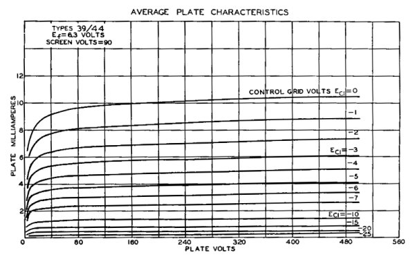 |
| Figure 2—Plate-characteristics graph for the Type 39/44 pentode. The presence of the connected-to-cathode suppressor grid disallows negative-resistance effects. |
The characteristic curves of a true pentode (Figure 2) show that inclusion of a third grid, the suppressor grid, between grid 2 and the plate strongly suppresses secondary-emission effects. Why the term true pentode? Because multiple lines of research also led to the marketing of "tetrodes with pentodelike characteristics" or "kinkless tetrodes"—which types at first included the 48 but went on to include a new class: the beam power tube, designs of which are generally characterized by:
| • | close alignment between the turns of fine wire that form a tube's control and screen grids |
| • | strategic, and relatively large, spacing between screen grid and plate to minimize secondary emission |
| • | the addition between screen grid and plate of special beam-forming or beam-confining plates to minimize secondary emission |
The first beam power tube introduced to market—in the States, at least—was RCA's 6L6, intended for use as a class A1 or AB1 AF power amplifier. As one of this page's opening epigrams reveals, its principle designer, Otto Schade of the Radio Corporation of America, knew from lab tests that the tube was capable of secondary-emission phenomena—but only under conditions not normally encountered during linear-amplifier operation.
And then RCA repackaged the 6L6 in a Mae-West-style glass envelope, equipped it with ceramic interelement insulation and a plate cap for higher-voltage operation, gave it a "stem shield" to reduce its grid–plate capacitance, and marketed it as the 807, a transmitting tube rated for everyday use in class C operation!
As Schade had indicated was true of the 6L6's second-emission-suppression design, negative resistance at low plate voltages and high negative control-grid biases is evident in the 807's published plate curves. And that's the problem with the 807: The 6L6 was designed for class A1 and AB1 operation in which its control grid never goes highly negative and its plate voltage does not drop far below that of the screen, and the 807, obviously just the 6L6 beam-suppression design with a top-cap plate connection, better insulation, stem shielding, and longer wires between its internal elements and its base pins, would, when used for class C amplification with its screen voltage supplied via a voltage-dropping resistor from the plate supply, routinely pass through, or even be ongoingly operated under, exactly the conditions Schade reported would result in secondary emission in the 6L6!
The stage was set for nearly two decades of negative-resistance-based misery for transmitter builders both amateur and professional—trouble made worse by the tendency of writers to ascribe the 807's negative-resistance-based instabilities (a known 6L6 bug) to poor application, through equipment design and construction, of the underlying design's relatively high transconductance (an 807 feature).
Stopping Beam Power Tube Parasitics: If at First You Don't Succeed...
We decided on the 2E26 because it is small, can be run at the 25 or 30 watts input that was wanted, and seems to be less prone to parasitic oscillations than its larger cousin. If some kind tube manufacturer ever brings out an 807 with short leads, it will be logical tube for this unit, but we played it safe for the present and used the 2E26.—Byron Goodman, W1DX, "A 1950 VFO Exciter," QST. September 1949 CE, pages 29–33.
Because an 807 has such a high transconductance and because it is almost impossible to get perfectly isolated return circuits to the cathode, a tendency toward instability may be encountered if the mechanical layout illustrated is not followed in every detail. But unless the design is particularly bad, the instability will be apparent only when both the load and the excitation are removed from the 807 stage. Because the instability will disappear when either excitation or load is applied to the 807, it should not be bothersome. However, if you so desire, the 807 stage can be made stable as the rock of Gibraltar at a small sacrifice in the 10- and 20-meter output by placing 50-ohm 1/2-watt carbon resistors in both the control grid and screen grid leads right at the tube socket (before connection to anything else). This method of taming 807's was suggested by W6BHO and works in all but the most stubborn cases.—W. W. Smith, W6BCX, "The '4-25' Exciter," Radio, December 1938 CE, pages 11–16
When keying in the crystal stage, or, for that matter, any stage ahead of the final amplifier, the stages following the keyed stage must be absolutely stable so that parasitics or output frequency oscillation will not occur when the excitation is rising on the beginning of each keying impulse. This type of oscillation gives rise to extremely offensive clicks which cannot be eliminated by any type of filter; in fact, a filter designed to slow up the rate at which signal comes to full strength may only make them worse.—W. W. Smith, W6BCX, and others, editors, The Radio Handbook, 10th edition (1946 CE), Chapter 7,"Transmitter Theory," page 186
The T-60 [transmitter] was prone to producing prolific parasitic oscillations sufficient to aggravate every 40M CW op in town, afflicting his receiver with CLICK CLICK CLICK (but much louder than key clicks, another animal entirely) every so many kHz. but the cure was cheap and easy: install an RF choke on the final. One of my Elmers, who was about 70 at the time, came zooming up my folks' driveway on his motorcycle, and made his way down to my basement shack, whereupon he said "Our friend Ernie is getting horrible parasitics from you all up and down 40 meters." He then removed the cover from the T-60, handed me the little RF choke, pointed at the two points to be soldered and said "solder the ends of this RF choke here, and here."—Kevin, WA7VTD, Knight Kit T-60 reviews, encountered May 6, 2010 CE, at http://www.eham.net/reviews/detail/5970#83593
A remedy which works in most cases is to insert a small 50-ohm resistor between the screen terminal and the by-pass capacitor.—Donald Mix, W1TS, "Unstable Signals," QST, August 1946 CE, pages 23–26, 126
Due to their relatively high slope these valves are prone to parasitic oscillation and it is advised that a small resistance on the order of 47 ohms, or less if essential, should be wired in series with the plate, directly connected to the top cap.—"Typical Operation at Radio Frequencies: General Recommendations," 807 Beam Tetrode Application Report, Standard Telephone and Cables Pty. Ltd., Sydney, Australia, 1954 CE.
Over and over again we see the tendency toward signal-frequency parasitics in beam tubes attributed to "high slope" and "greater power sensitivity"—even though true pentodes of like transconductance much less commonly exhibited the problem.
Many 6CL6s I have used, all the way from audio to six meters, and nary a whimper or any taking-off-unbidden. Not so with the 5763. Physicist friend who long ago forgot more than I'll ever know about thermionic valve design said to me once, "Look at the RCA data on a 5763. It'll tell you the tube was designed as an oscillator-multiplier. And if you give it half a chance, it'll oscillate or multiply."—John McAulay, Glowbugs mail reflector, May 20, 1997 CE
So incompletely known and explained were intrinsic-negative-resistance-based effects in the 807 and other beam power tubes that ham-handbook coverage of instability cures commonly approached the necessary troubleshooting with shotgun/scattergun techniques, through which multiple cures, some appropriate for intrinsic-negative-resistance causes and others not, were applied in the hope of finally finding something, anything, that worked:
If...the stage under investigation uses a beam-tetrode tube, negative resistance can exist in the screen circuit of such tubes. Try larger and smaller screen by-pass capacitors to determine whether or not they have any effect. If the condition is coming from the screen circuit an audio choke with a resistor across it in series with the screen feed lead will often eliminate the trouble....It may be said in general that the presence of low-frequency parasitics indicates that somewhere in the oscillating circuit there is an impedance which is high at a frequency in the upper audio or low-r-f range. This impedance may include one or more r-f chokes of the conventional variety, power-supply chokes, modulation components, or the high impedance may be presented simply by an RC circuit such as might be found in the screen-feed circuit of a beam-tetrode amplifier stage. Beam-tetrode stages, particularly those using 807-type tubes, will almost invariably have one or more v-h-f parasitic oscillations unless adequate precautions are taken in advance....These considerations involve the facts that a beam-tetrode amplifier stage has a greater power sensitivity than an equivalent triode amplifier, such a stage has a certain amount of screen inductance which may give rise to trouble, and such stages have a small amount of feedback capacitance....Basically, parasitic oscillations in beam-tetrode amplifier stages fall into two classes: cathode-grid-screen oscillations, and cathode-screen-plate. Both of these types of oscillation can be eliminated through the use of a [parallel RL] parasitic suppressor between the screen terminal of the tube and the screen by-pass capacitor. Such a suppressor has a negligible effect on the screen at the operating frequency....The grid-screen oscillations may occasionally be eliminated through the use of a [parallel RL] parasitic supressor in series with the grid lead of the tube. The screen-plate oscillations may also be eliminated by inclusion of a [parallel RL] parasitic suppressor in series with the plate lead of the tube. A suitable grid suppressor may be made of a 22-ohm 2-watt Ohmite or Allen-Bradley resistor wound with 8 turns of no. 18 enamelled wire....The parasitic suppressor of the plate circuit of a small tube such as the 5763, 2E26, 807, 6146 or similar type may consist of a 47-ohm carbon resistor of a 2-watt size with 6 turns of no. 18 enamelled wire wound around the resistor....A series of rapid dots should be sent, and the frequency spectrum for several megacycles each side of the carrier frequency carefully searched. If any vestige of parasitic is left, it will show up as an occasional "pop" on a keyed dot. This "pop" may be enhanced by a slight detuning of either the grid or plate circuit....If the parasitic shows up, it means that the stage is still not stable, and further measures must be applied to the circuit. Parasitic suppressors may be needed in both screen and grid leads of a tetrode, or perhaps in both grid and neutralizing leads of a triode stage. As a last resort, a 10,000-ohm 25-watt wirewound resistor may be shunted across the grid coil, or grid-tuning condenser of a high-powered stage. This strategy removed a keying pop that showed up in a commercial transmitter operating at a plate voltage of 5000.—William I. Orr, W6SAI, editor, The Radio Handbook, 14th edition, 1956 CE, pages 295–300.
But "an occasional 'pop' on a keyed dot" is almost certainly not a VHF-parasitic phenomenon, but a low-frequency or audio effect if it's heard along with the wanted signal at or near the frequency of the wanted signal.
Simple methods of suppressing v.h.f. parasitics are available and one or other of them should always be used as a safeguard. The most commonly adopted method is the inclusion of "stopper" resistances in the leads to the valve electrodes. These are connected directly at the valve socket or at the cap of the valve. These resistances should be of carbon and should not have a higher value than is necessary to stop the parasitic oscillations; suitable values are 10–100 ohms; for [the grid stopper] and 10–22 ohms; for [the plate stopper]. The stopper resistance in the screen circuit is usually of about 50 ohms; and is included because there is often quite a large mutual conductance between the control grid and screen, with the consequent possibility of v.h.f. parasitics being generated in the screen circuit. The presence of this resistance, while preventing the screen from being properly earthed at the carrier frequency, is unlikely to make neutralization necessary. If difficulty is in fact encountered, the use of two or more bypass capacitors of different values in parallel (e.g. 0·01 μF and 100 pF) to give a low impedance over both h.f. and v.h.f ranges may be tried as an alternative to the use of the screen stopper.—The Radio Society of Great Britain Amateur Radio Handbook, Third Edition (1961 CE), pages 186–187.
Time out for a reality-check datapoint on the losses involved with plate and screen stoppers: In a stable, well-neutralized, parasitic-free 1631 (12.6-V 6L6) class C vacuum-tube amplifier operating at 3.55 MHz, adding a 47-Ω plate stopper reduced the output power from 7.98 W to 7.69 W—that is, by 0.16 dB. (I had to retune the stage slightly to remaximize its output after adding the resistor.) Relative to the original figure of 7.98 W, operating the stage with a 100-Ω screen-grid stopper and the 47-Ω plate stopper reduced the output power to 7.76 W, a reduction of only 0.12 dB. Recognizing that adding the screen stopper might affect the stage's neutralization, I determined that no instability could be detected, even when keying the entire transmitter without drive and varying the output stage's TUNING capacitor through its full range. At 7 MHz, the stage's output with plate and screen stoppers installed was 7.12 W, fully in keeping with my earlier characterization of the rig's output as "8 W on 80 and 7 W on 40."
What the Physicist Saw
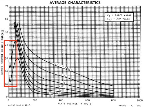 |
| Figure 3—Graphing the average screen characteristics of the 7984 beam power tube, purpose-built for class-C RF service in General Electric's Progress Line of base and mobile transmitter-receivers, reveals that the 7984's screen exhibits significant negative resistance when the tube's plate voltage drops well below that of the screen with the grid highly negative. Despite this characteristic, the 7984, a compact, single-ended alternative to the 6146, was successfully applied not only in the Prog Line and similar products but also as in modulator and RF power amplifier service in broadcast radio and television transmitters. Screen and/or plate negative resistance is intrinsic to all power tetrodes; the trick is to apply these tubes with this proclivity kept in mind and allowed for. |
 |
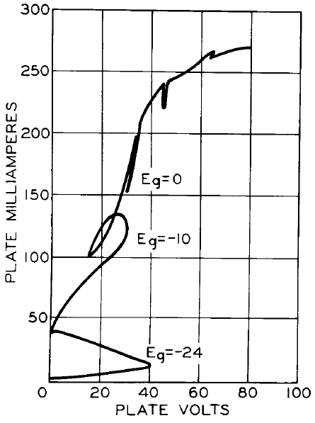
| Figure 4—A possible driver for the relative inexpensiveness of the xBK5 beam power tube on Ebay: At plate voltages well below the screen voltage—250 in all cases graphed here—the 6/12/25BK5's plate exhibits significant negative resistance when the tube's grid is more negative than −5 or −-6 volts, −5 being the "typical operation" value. Unlike the 6L6, which had to be operated with its grid far more negative than its usual class-A-bias value for negative-resistance effects to set in, the xBK5 would have run into trouble with its grid only a little more negative than usual—say, as a result of the value of its (likely carbon-composition) cathode-bias resistor increasing with age or as a result of soldering heat. |
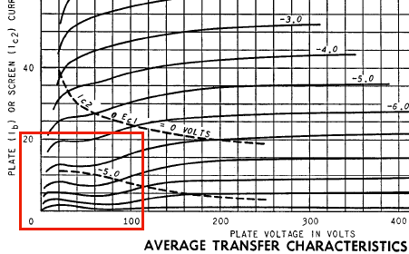
Zeroing in on the 5763 plate curves—and the plate curves of a miniature two-beam-tubes-in-one-envelope RCA twin-"pentode" design so prone to screen-negative-resistance instability problems that even its one-paragraph description in the fifth edition of the RCA Transmitting Tubes Manual recommends that a 100-Ω resistor be used between the tube's screen terminal and its bypass capacitor:
It is recommended that a 100-ohm resistor be connected in series with grid No. 2, as close as possible to the socket, to prevent the generation of parasitic oscillations.—"Operational Considerations," 6939 twin pentode, RCA Transmitting Tubes, TT-5 edition.
Eye-opening research: A college student's electrical engineering honors thesis provides eye-opening graphs depicting negative resistance in the 5763, 6146, and other types. Writes she of the 5763:
With the suppressor grid hooked to the screen grid, the tube operates like we would expect, similar to the 6AU6 and the 6CL6 as discussed before. I used a 5.8 volt bias, 92 volt potential across the screen and up to 90 volts potential across plate. These conditions produced a rather pronounced secondary emission. The effect begins to appear at a potential across the plate of around 10 volts, and then disappears at a plate potential of around 60 volts. Interestingly, in this tube I was not able to turn the secondary emission effect off. Grounding the third grid only succeeds in reducing the effect, not eliminating it. That means that the tube produces secondary emission even during normal operation as a pentode. The effect begins when the plate potential reaches about 5 volts and then ends when the plate potential reaches about 125 volts. Apparently, for the typical applications of the 5763 tube, secondary emission does not adversely affect the operation.
Or not not, and, as with the 807, users of the tube merely put up with artifacts of the effect, perhaps thinking that their circuit designs and/or implementation(s) were flawed.
Why neutralization can't stop parasitics caused by intrinsic negative resistance: Intrinsic negative resistance is a one-port effect that requires only a two-terminal connection to the negative resistance of some form of sufficiently low-loss reactive energy storage. An inductor, a capacitor, a series or parallel combination of inductance and capacitance, or a sufficiently low-loss distributed (transmission-line) equivalent of any of these, will do.
My own crazy-oscillations-in-a-final-amplifier story: An encounter with a 10JA5 Class C stage that oscillated so strongly at AF and RF that I could hear the parasitics acoustically—likely as a result of bypass and/or blocking capacitors acting as piezoelectric speakers.
How users of modern power tetrodes do it right: Modern power tetrodes do not include beam-forming plates and are applied with much more attention given to supply and management of screen voltage and negative resistance. From the datasheet for the Svetlana 4CX7500A tetrode:
The screen current may reverse under certain conditions and produce negative indications on the screen current meter. This is a normal characteristic of most tetrodes. The screen power supply should be designed with this characteristic in mind, so that the correct operating voltage will be maintained on the screen under all conditions. A current path from the screen to cathode must be provided by a bleeder resistor or a shunt regulator connected between screen and cathode and arranged to pass approximately 10% of the average screen current per connected tube. A series regulated power supply can be used only when an adequate bleeder resistor is provided.
—a passage very similar to wording in Ian White, G3SEK, "Power and Protection for Modern Tetrodes," QEX, October 1997 CE, page 15. Might we be able to tame negative-resistance-related parasitics in first-generation beam-power tetrodes by applying today's shunt screen-voltage-regulation methods?
"You've got to ac-centuate the positive, e-liminate the negative...": Inserting "stopper" resistors can quell intrinsic-negative-resistance-based parasitics because negative and positive resistances sum directly. Inserting a positive resistance in series with a negative resistance moves their net value toward zero (and positive) resistance by the ohmic value of the stopper. Stopper resistors aren't about "killing Q," as we sometimes see their mechanism characterized; they're about rendering the resistance of a negatively resistive circuit zero or positive—or even just insufficiently negative such that oscillation-killing losses in associated circuitry are not counteracted.
 |
| Figure 5—How to tame intrinsic-negative-resistance-based parasitics in the 807 with grid and screen stopper resistors as told in the final paragraph of W. W. Smith, W6BCX, "The "4-25" Exciter," Radio, December 1938, pages 11–16. No, "high transconductance" is not the cause. (Students of computing jargon, note this use of bug to mean "flaw or defect" before the advent of electronic digital computing. "Ironing out the bugs" was originally about killing lice in clothing.) |
Counterattack (and Confirmation) by the Anti-Sniveteers
Enter post-World-War-2 television. Painting each frame of a television picture requires that the stream of electrons produced by the electron gun of the picture tube be driven from side to side (horizontal deflection) and up and down (vertical deflection), which operations require that strong current pulses be driven through deflection coils mounted around the neck of the picture tube. In particular, horizontal deflection amplifier service required tubes that were, per Ludwell Sibley in his Tube Lore, "essentially small transmitting tubes with continuous-duty dissipation ratings of 18 watts and up"—tubes "designed to put out slam-bang 16-kHz sawtooth signals with multi-kilovolt flyback pulses." What device could be better suited for this job than the beam power tube?
With both cathode power and high-voltage capability considered, the biggest, baddest receiving-class beam power tube available was the 6L6, the transmitting equivalents of which (the 807 and its 12.6-V-heater sibling, the 1625) had, with their top-cap plate connection and ceramic interelement insulation, already been modified toward withstanding the high-voltage pulses involved in horizontal-deflection service. (Per Sibley, the 6L6 had even been applied in horizontal-amplifier service for prewar television as the plate-cap-equipped 6AL6 of 1939 CE.) Soon the 807, with a black Bakelite octal base replacing the more-RF-friendly but more-expensive five-pin Micanol base of the war years, was re-characterized for horizontal-deflection service and re-released as the 6BG6. Further economization (out went the ceramic insulators and stem shield) and a heater-voltage variant for series-heater-string use (the 19BG6) followed. Soon, beam power tubes with higher-power heaters and higher-perveance cathodes, designed specifically for horizontal-deflection service, came to market, and the beam-power-tube subclass now known as the sweep tube was born. But there was one small problem, as Figure 6 shows.
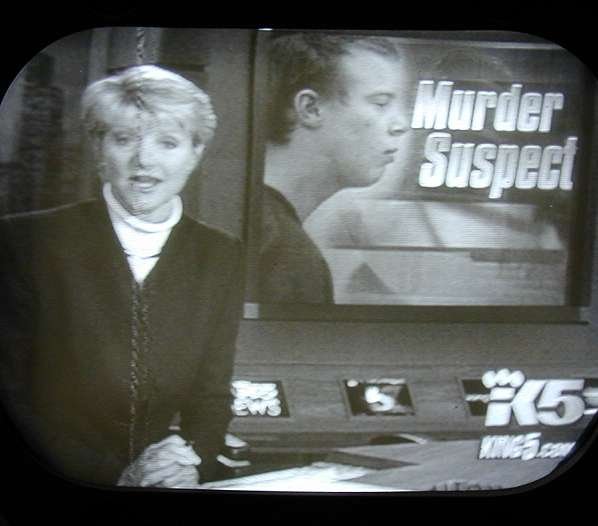 |
| Figure 6—The picture in early television sets was sometimes marred by an in-picture vertical line referred to as snivets. That this defect occurred in each line of the picture, and at the same point in the sweep of each line, indicated that its underlying cause occurred the same way at the same relative time in the progress of every horizontal scanning cycle.(Photograph used by permission of Philip I. Nelson, Phil's Old Radios, http://antiqueradio.org/, Copyright 2015.) The horizontal-amplifier tube involved was a 6BG6—a repurposed 6L6 equipped with a plate cap.) |
Three approaches to solving snivets interference were generally employed, at least two of which were all too familiar to hams struggling with parasitic pops, key clicks, distortion, and wideband noise in beam-tube power amplifier stages. These nostrums included—at first—installing a stopper resistor between the horizontal-amplifier screen connection and the outside world; installing a small inductor between the horizontal-amplifier plate connection and the outside world; and/or trying different individuals of the specified horizontal-amplifier-tube type until one was found that lessened the interference or made it go away. A fourth option—applying a relatively low positive voltage to the beam-forming plates of the horizontal-deflection-amplifier tube—would be made available by tube manufacturers when tube engineers at last understood why and how snivets interference occurred.
"Another theory holds that snivets interference is caused by a form of Barkhausen oscillation. This theory is logical because the plate voltage swings appreciably below the screen-grid (grid no. 2) voltage in many receivers. This condition is especially severe in modern flyback transformer designs which drive the plate voltage as far into the knee region as possible. An example of the load line of a horizontal-deflection tube illustrates this phenomenon quite well. The most familiar load line to most engineers is that drawn for resistance-coupled amplifiers, which is simply a straight line. Figure 7 shows the load line of a typical deflection tube in a television receiver which exhibited strong snivets. Is it any wonder that interference resulted?"—from W. E. Babcock, "Circuit Troubles Caused by Unusual Tube Effects," Electron Tube Design (RCA: Harrison, New Jersey, 1962 CE), pages 736–742.
 |
| Figure 7—Load-line graph for a 25CD6 beam power tube operating as a horizontal deflection amplifier. Wrote W. E. Babcock of this presentation in RCA's 1962 CE Electron Tube Design, "Is it any wonder that interference resulted?" |
Current Division in Region A—Special precautions must be taken to ensure current stability in region A (Figure 8) to permit tube operation where a portion of the plate-voltage swing is below screen-grid potential. Regeneration resulting from a negative slope in the plate current can cause extraneous oscillations. [The author footnotes Schade's "Beam Power Tubes," Proceedings of the Institute of Radio Engineers, Volume 26, Number 2, pages 137–181—the source of the quote at the beginning of this page—here.] Current division in Region B—All tetrode structures exhibit stable current characteristics in this region.—from J. W. Gaylord, "Some Factors Affecting the Design and Application of Small Power Tubes," Electron Tube Design.
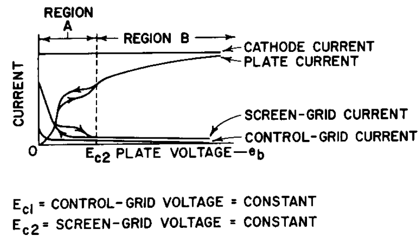 |
| Figure 8—Graph of typical tetrode current characteristics from J. W. Gaylord, "Some Factors Affecting the Design and Application of Small Power Tubes," Electron Tube Design. Hysteresis in the plate and screen curves indicates that both elements exhibit negative resistance in region A. When such intrinsic negative resistance is present, connecting either element to a means of reactive energy storage—lead inductances, internal and external, in conjunction with external reactances that provide a path to common, are sufficient—can result in oscillation. |
And Yet They Knew
There it was in the buried-by-two-jumps last paragraph of the first ARRL-staff-written article about the 807—the repurposed-6L6 transmitting tube that would bedevil a generation of amateur and commercial builders alike with negative-resistance-based parasitic oscillations from audio to VHF:
It has been said that tubes of this type, because of their extremely high power sensitivity, are prone to parasitic oscillations, particularly of the type involving the screen circuit. In the rig shown, no tendency of this sort developed. Should parasitics be present, however, the recommended cure is to insert a non-inductive resistor of about 100 ohms in series with the screen right at the tube socket and on the screen side of the bypass condenser. This will have no measurable effect on the normal plate output.—George Grammer, W1DF, "Operating Notes on the Transmitting-Type Beam Power Tube," QST, December 1936 CE
In that first ARRL-official caution that the 807 might be unstable by design, we see also a museum-quality instance of veiledly simultaneously praising the tube by attributing its negative-resistance flaws to "extremely high power sensitivity." If 6L6 designer Otto Schade's own words about the negative resistance inherent in the tube's design were not sufficiently tonic, we can understand through researching the brief dynatron-oscillator vogue surrounding the much-lower-gain 24 tetrode and the hard-to-defeat negative-resistance proclivities of the creatively characterized 5763, and by studying the anti-snivets struggles of televison-receiver engineers and technicians, that the mere absence of a suppressor grid and the correct operating conditions are all that's necessary to produce significant, practically leveragable negative resistance in a tetrode. It would be another decade before QST again officially (and again reluctantly) recommended screen stoppers to tame the 807, and over a decade and a half before RCA largely put users of the 807 out of their misery with the introduction of the equivalent-and-then-some 6146.
Epilogue
Now that we know how intrinisic negative resistance in beam power tubes can support parasitic oscillation, we also know that a variety of techniques are available to offset its effects:
| • | Modify the tube's operating conditions so that negative-resistance effects are less likely to occur, including operating the tube as a linear amplifier rather than in class C. |
| • | Insert stopper resistors (Figure 9) and/or inductors—preferably resistors, as their positive resistance directly offsets negative resistance—between a tube's screen and/or plate connections and the outside world |
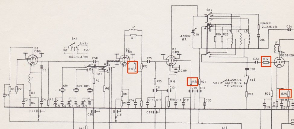 |
| Figure 9—Schematic detail from a Philips transmitter showing screen stopper resistors applied to E80L pentodes and a QE 08/200 beam power tube. (from Masteroscillator's "6DQ6 and Dynatron" page (http://www.masteroscillator.info/cgi-bin/CSA/tw201/I/en_US/Blog/Dynatron_6DQ6) |
| • | Use a tube type, and/or an individual tube, less prone to negative-resistance effects |
| • | Use a tube type that affords a separate beam-forming-plates connection, and apply positive bias to the beam-forming plates |
| • | Explore powering the tube screen by means of an electronically-regulated power supply |
References
807 Beam Tetrode Application Report, Standard Telephone and Cables Pty. Ltd., Sydney, Australia, 1954 CE.
The Amateur Radio Handbook, Third Edition (1961 CE), Radio Society of Great Britain.
W. E. Babcock, "Circuit Troubles Caused by Unusual Tube Effects," Electron Tube Design (RCA: Harrison, New Jersey, 1962 CE), pages 736–742.
Byron Goodman, W1DX, "A 1950 VFO Exciter," QST. September 1949 CE, pages 29–33.
George Grammer, "Operating Notes on the Transmitting-Type Beam Power Tube," QST, December 1936 CE, pages 28–29, 70, and 72.
J. W. Gaylord, "Some Factors Affecting the Design and Application of Small Power Tubes," Electron Tube Design (RCA: Harrison, New Jersey, 1962 CE), pages 743–762.
General Electric Corporation, 6JN6 datasheet, April 1964 CE.
General Electric Corporation, 6LB6 datasheet, January 1967 CE.
Masteroscillator, "6DQ6 and Dynatron," http://www.masteroscillator.info/cgi-bin/CSA/tw201/I/en_US/Blog/Dynatron_6DQ6.
David D. Meacham, W6EMD, "Understanding Tetrode Screen Current," QST, July 1961 CE, pages 26–29.
Donald Mix, W1TS, "Unstable Signals," QST, August 1946 CE, pages 23–26 and 126.
Don Mix, W1TS, "Amplifier Instability in Transmitters," QST. June 1948 CE, pages 19–24 and 110.
Angie Myers, "Saturation and Secondary Emission of Electrons in a Vacuum," http://faculty.frostburg.edu/phys/latta/ee/2ndemission/tubefront.htm.
Philip I. Nelson, "Hallicrafters Model T-67 Television (1948)," http://antiqueradio.org/hallit-67.htm.
William I. Orr, W6SAI, editor, The Radio Handbook, 14th edition, 1956 CE, pages 295–300.
PL-504 datasheet, Philips, September 1970.
O. H. Schade, "Beam Power Tubes," Publication ST-59 (RCA: Harrison, New Jersey, March 1938 CE).
RCA Manufacturing Company, RCA Cunningham Radiotron Radio Tube Manual, edition RC-12 (Harrison, New Jersey, 1934 CE).
Ludwell Sibley, Tube Lore (Flemington, New Jersey, 1996 CE).
W. W. Smith, W6BCX, "The '4-25' Exciter," Radio, December 1938 CE, pages 11–16.
W. W. Smith, W6BCX, and others, editors, The Radio Handbook, 10th edition (1946 CE), Chapter 7,"Tansmitter Theory," page 186.
O. P. Susmeyan, W1BLH, "Experiments with Dynatron Oscillators," QST, September 1930 CE, pages 33–35.
RCA Transmitting Tubes, Technical Manual TT-5, Antique Electronic Supply reprint.
Ian White, G3SEK, "Power and Protection for Modern Tetrodes," QEX, October 1997 CE, page 15.
| Revised February 27, 02021 CE. | Content not otherwise attributed is copyright © 2009–2021 by David Newkirk. All rights reserved. |