W9VES I (01935–01969) and W9VES II (01996–02014)
The amateur radio call sign W9VES has been assigned to—held by, as ham radio operators like to put it—only two people, of whom I was the second. My maternal uncle, Phil Simmons, was the first W9VES, and from 01996 to 02014—when I began operating W9BRD III—I enjoyed my amateur radio in celebration of him. By mid-02008, when this page was first created, the expanding sphere of Effect created by his first transmission in 01935 spanned a diameter of 146 light-years.
|
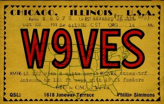
| A W9VES QSL card from 01935. The transmitter used a Type 45 triode tube operating at 8 W input in a TNT (tuned, not tuned) circuit, a special case of the tuned-plate, tuned-grid oscillator; that four-tube TRF (a receiver consisting of a regenerative detector preceded by a tuned RF stage and followed by two stages of audio amplification) would have been a loan from 14-year-old Phil's friend and chief engineer, George H. ("Bud") Nibbe, W9NUF. The station location at 1618 Juneway Terrace overlooked southern Evanston across the northernmost back alley in Chicago.
|
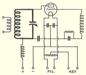 |
| The schematic diagram of Phil's TNT transmitter, a single-tube oscillator, would have looked much like this. The plate circuit (bold lines) determines the oscillator's frequency; the grid circuit is haphazardly tuned by an inductance that resonates at a frequency determined by its own distributed capacitance and the tube's grid-to-filament capacitance.
|
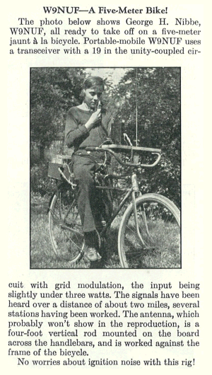 |
| Phil's friend and chief radio engineer George H. "Bud" Nibbe made print in "Strays" on page 52 of October 01935 QST with his 5-meter-transceiver-equipped bike. Nibbe would die at 42 in 01963; Phil, six years later, at 47. |
|
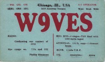
| A W9VES QSL card from 01939, self-typeset and -printed on a Kelsey hand press later owned by brother-in-law-to-be Rod Newkirk, W9BRD. By this time Chief Engineer Nibbe had Phil's transmitting facilities sporting a four-stage rig that included a 100-W-input RF power amplifier based on a Taylor TZ-40 triode (erroneously reported on the card as a T-40, the TZ-40's lower-μ sibling); the receiver was by now a three-tube TRF regen. The card is smudged because young Phil was too impatient to let the cards dry sufficiently after the black-ink run.
|
|
|
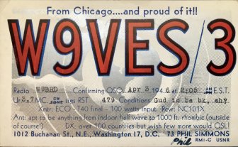
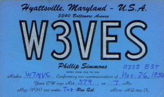
| Postwar, Phil attended the University of Illinois with Bud Nibbe and later traded W9VES for W3VES while working in United States government communications in the Washington, DC, area. (Immediately postwar, the tagline on Phil's W9VES/3 card—"From Chicago—and proud of it!"—had been a source of comic chagrin as Maryland-DC locals had ribbed him that he seemed to be glad to be out of the place!)
|
|
|
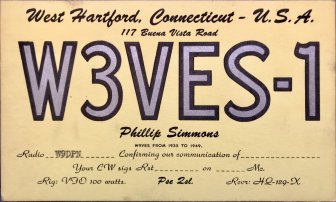
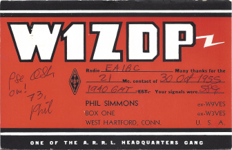
| From 01954 to 01959, Phil doffed W3VES for W1ZDP and worked in the American Radio Relay League Headquarters Communications Department, tallying, and crafting writeups of, on-air ARRL contests, and rooming at Rilla Selden's old farmhouse at 117 Buena Vista Road, West Hartford—hamdom's legendary Selden Hill.
|
Following a Long-Abandoned Thread as W9VES II
While building up the gumption to take the Novice amateur radio license examination as a teenager, I bought a little yellow Editors and Engineers paperback book, Easy to Build Ham Radio Projects by Charles Caringella, W6NJV. Its simplest construction project, "Novice Transmitter for 80 or 40 meters," consisted of a grid-plate crystal oscillator that used a 5763 transmitting beam power vacuum tube. By mail, from Lafayette Radio on Long Island, I bought a small aluminum chassis to house it. The rest of its components came from the parts collection—junkbox in ham-radio speak—of my father, who had operated amateur radio station W9BRD since the late 01930s.
 |
| Front cover of Charles Caringella, W6NJV, Easy-to-Build Ham Radio Projects (New Augusta, Indiana: Editors and Engineers, June 01967).
|
|
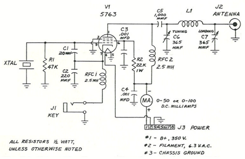
| Schematic diagram of the one-tube transmitter by Charles Caringella, W6NJV. The circuit is a "grid-plate" (aperiodic tri-tet) oscillator. The popular Ameco AC-1 beginner's transmitter used a 6V6GT tube in essentially the same circuit. (For practical tips on using and improving this circuit, see this site's "Celebrating the One-Tube-Oscillator Transmitter" page.)
|
Although I completed the transmitter to the point of dimly lighting an incandescent lamp with its radiofrequency (RF) power output, I never went on the air with it. I was persuaded by my ham-radio mentor—my Elmer, by ham-radio tradition—that I would be disappointed with its low power. He was accustomed to using an outdoor, tower-mounted antenna and running as much power as the law allowed, and he knew that I would begin my ham career with my father's quasi-indoor antennas. And so I put the little 5763 transmitter aside, later going on the air for the first time, as WN9CJS, Norridge, Illinois (near Chicago), with a more-powerful Lettine Model 240 transmitter, once owned by the first W9VES. The Lettine used a 6L6GB crystal oscillator driving an 807 power amplifier, and likely put out perhaps six times the RF power of the 5763 oscillator.
Later, per an article in QST (Donald Mix, W1TS, "A Simple Transmitter for the Beginner," Beginner and Novice, QST, September 01968, page 22), I would add a 6C4 triode Pierce crystal oscillator to the 5763 circuit and enjoy many solid contacts and several radio adventures with the modified transmitter, including working KH6ALD, Hawaii, on 40 meters during a middle-of-the-night thunderstorm. (I would also discover that the transmitter still acted as a crystal oscillator with the 6C4 stage disabled, a common characteristic of the Boosted Pierce.) And later still I would discover, using transmitters with output powers from 6.3 milliwatts to 20 watts or so, some using transistors but most (including the 6.3-mW job) using tubes, that I could have inexhaustible fun with low transmitting power as long as my antenna and receiver allowed me to hear signals down to the band noise.
Thinking this all over, I decided that I would rebuild the transmitter that I had forsaken: the 5763 grid-plate crystal oscillator from Easy-to-Build Ham Radio Projects. Based on my ham radio experience in the meantime, I modified the circuit somewhat. For example, I used voltage-regulator (VR) tubes rather than a series voltage-dropping resistor to supply screen-grid voltage to the 5763, as I knew that this would stabilize my operating frequency by generally reducing, and reducing changes in, RF heating of the crystal. (It would be 2019 before I learned that the only change necessary to reduce crystal heating in this and similar one-tube-crystal-oscillator-transmitter circuits is to reduce the value of its grid 1 resistor from 47 kΩ to 10 kΩ.)
My revised station, temporarily operating under the call sign AB2WH, was therefore initially configured as follows. The 5763 grid-plate oscillator served as the transmitter. An ongoingly modified Kenwood R-599A served as the receiver. A relay-and-toggle-switch-based transmit-receive (TR) switch, built into the steel box from a defunct computer power supply, switched the antenna between receiver and transmitter, and also switched the transmitter between dummy antenna and real antenna. The dummy antenna, built into a butter-cookies tin, was a 50-ohm resistance consisting of five 10-ohm, 10-watt Radio Shack power resistors connected in series, with the inductive reactance of this resistance "tuned out" with a squeaky old two-section broadcast-receiver tuning capacitor, its sections paralleled, wired in series with the resistors. The real antenna was an outdoor, low random wire, its electrical length somewhere between a quarter wavelength and a half wavelength at 3.5 MHz. I tuned out its reactance with an L impedance-matching network made from a 280-pF capacitor and a homemade inductor made from #14 black-jacketed THHN house wire wound on a sparklingly transparent polycarbonate drinking glass and tapped at intervals so I could adjust its inductance by short-circuiting part of it with a wire equipped with an alligator clip. The matching indicator was a Monimatch Mark IV (Lewis G. McCoy, W1ICP, "The Monimatch Mark III and Mark IV," Beginner and Novice, QST, September 01964, page 20), built into two International Coffees tins. I keyed the transmitter with the straight-key portion of the Brown Brothers CTL-B combination paddle/straight key I've used since my Seattle days as AK7M.
At 3.5 MHz, the transmitter put out 4 watts, a value based on measurements made with a digital multimeter and a homemade RF peak voltmeter as described in Wes Hayward, Rick Campbell, and Bob Larkin, Experimental Methods in RF Design. On my first-ever call with it, a 3.550-MHz CQ in the wee hours of March 11, 02007, I worked W8TY, Jon, in Elida (near Lima), Ohio.
My final contact as W9VES II—with Bobby, AK4JA, of Newnan, Georgia, at 7120 kHz using the W9VES-W9BRD Changeover Transmitter—ended at 0150 Eastern Daylight Time on June 24, 02014.