We know from one of his early QSL cards that the first W9VES almost certainly began operation in the latter half of 1935 CE with a transmitter that used a 45 tube (a power triode intended for use in AM broadcast receivers) as a tuned, not-tuned (TNT) oscillator. In conversations with my dad, the second W9BRD, I learned that in 1936 CE Phil was likely using a single-tube crystal-oscillator-only transmitter based on a 47 power pentode (also intended for use in broadcast receivers, but later also marketed as a transmitting tube [RCA 1610]).
From his writings in K9YA Telegraph, later included in The Rod Newkirk Collection, we know that W9BRD first went on the air in late 1937 CE at 40 meters with "a 6L6 and two crystals."
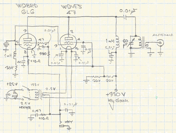
Based on these understandings, I decided to celebrate my call-sign transition from W9VES to W9BRD on the air with a transmitter that allowed me to change from "W9VES 1936" to "W9BRD 1937" merely by changing a tube. Figure 1 shows its circuit.

|
| Figure 1—Schematic diagram of the W9VES-W9BRD Changeover Transmitter. The circuit is a tuned-plate, crystal-grid (TPXG) oscillator. Using a 47 tube (as W9VES did in 1936 CE), the transmitter puts out 3 watts at 40 meters (for me, generally 7120 or 7121 kHz). Unplugging the 47 and plugging in a metal 6L6 turns the circuit into W9BRD's first transmtter (December 1937 CE) and increases its output power to 5 watts. Retuning is necessary with the tube change. The 47's cathode is filamentary and operates at 2.5 V; the 6L6's cathode is indirectly heated at 6.3 V. (A 1631 can also be used by increasing the heater supply to 12.6 V.) The 100-Ω resistor and 0.47-μF capacitor in series to common across the KEY jack suppress an RF click on keying BREAK. |
| Revised July 2, 2014 CE. | Copyright © 2007–2014 by David Newkirk (david.newkirk@gmail.com). All rights reserved. |
| home |