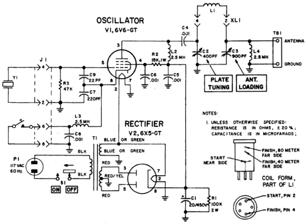
For many radio amateurs from the 01930s until the early 01970s, the single-tube crystal-oscillator transmitter was the bare-minimum means of getting on the air. Figure 1 shows the schematic diagram of a well-known example of this transmitter type: the Ameco AC-1, now highly valued as a nostalgic buildable and/or collectible even by hams who didn't use one as beginners.
|
| Figure 1—Schematic diagram of the Ameco AC-1 transmitter. This is a grid-plate (aperiodic tri-tet) oscillator—a Colpitts crystal oscillator in which the 22- and 220-pF capacitors associated with the tube's control grid and cathode form a voltage divider that provides the positive feedback necessary for oscillation. In an earlier version, the grid 1 resistor (R3) was 68 kΩ instead of 47 kΩ, the screen voltage-dropping resistor (R2) was 18 kΩ instead of 15 kΩ, and the power supply used capacitor-choke-capacitor filtering instead of the single-capacitance (C1, 20 μF) filtering shown here. |
Things to Do and Not Do with Your Ameco AC-1 Transmitter
Do tune the transmitter for maximum output power—not plate-current dip—and then slightly retune for best keying. Maximizing output at plate-current dip is about tuning an amplifier. An oscillator is an amplifier that supplies its own input signal, the level of which varies with output tuning and loading. As a further complication, best keying quality commonly does not coincide with maximum output in keyed oscillators. Therefore the "dipping and loading for max" tuning approach that's correct for "just an amplifier" is incorrect for optimum tuning of a single-tube-oscillator transmitter.
Do experiment with reducing the value of R3, the 47- or 68-kΩ grid resistor, to decrease chirp and yoop. An R3 of 5.6 kΩ has worked well in experiments at W9BRD. Depending on the crystal in use, keying may be somewhat "lighter" as a result of this modification—the oscillator will take a bit longer to start oscillating on key down and will stop oscillating a little sooner on key up—but if you're sending with a straight key while monitoring your own transmitted signal, you'll compensate for this condition automatically. (Thanks to Monte Allen, W9BMW, for this lower-value-grid-1-resistor tip, which I discovered in the page at https://www.qsl.net/wb1gfh/ameco1.html. It entirely supersedes other commonly applied techniques to reduce chirp in single-tube-crystal-oscillator transmitters, including adjusting feedback by changing values in the circuit's Colpitts voltage divider and regulating the voltage supplied to the oscillator-tube screen [grid 2].)
Do connect a 150-kΩ resistor (or a lower value, as necessary) across the keying line to keep the KEY UP voltage between the oscillator tube cathode and common to a value that does not endanger the tube's heater-cathode insulation. Assuming that the oscillator grid-1 resistor is connected between grid 1 and common—as is so in all of the schematic diagrams in this page—the open-circuit (KEY UP) voltage seen during cathode keying is the positive equivalent of the tube's cutoff bias. The Ameco AC-1 and W6NJV oscillator circuits shown in Figures 1 and 2 in this page use just series voltage-dropping resistors between grid 2 (the screen) of their oscillator tubes and the high-voltage supply. Because a voltage-dropping resistor can only reduce voltage if current flows through it and because there is essentially no current flow through the screen resistor in the KEY UP condition, grid 2 of the oscillator tubes floats nearly up to the high-voltage-supply level when the tube is not conducting. This causes the tube's cutoff voltage to soar far above what it would be were the grid 2 voltage held more constant (as with a voltage-regulator tube or resistive voltage divider), endangering the tube's heater-cathode insulation (which is commonly rated to withstand no more than 100 V dc). Connecting a high-value resistor between cathode and common allows the tube to conduct a very small current, resulting in enough voltage drop through the screen voltage-dropping resistor to reduce the screen voltage to a level that keeps the tube's open-circuit cathode voltage to a safe value. For example, with a 6DS5 operating in the AC-1 (Figure 1) circuit with a 15-kΩ screen dropper and a high-voltage supply of 325 V KEY UP, the oscillator tube's KEY UP cathode voltage was 106 without 150 kΩ between the keying line and common, and 35 V with the protection resistor in place. 35 V across 150 kΩ equates to a current flow of just 0.2 mA through the tube—not nearly enough to allow the tube to oscillate with the key up.
Do connect a 1-μF plastic-film capacitor (100 V rating or higher) in series with 330 Ω across the keying line to eliminate the strong click on key up (BREAK).
Do not increase the value of C1, the 20-μF power-supply filter capacitor, beyond 22 μF without also modifying the power supply to use solid-state rectifiers. To materially improve ripple reduction in the AC-1's simple RC power-supply filtering, you would have to increase the value of C1 by a factor of four or more. Doing this would greatly shorten the life of rectifier tube V2 as a result of increased peak current through the 6X5's diodes. If you want to use a high-value capacitor at C1, replace V2 with suitable solid-state diodes—say, 1N4007s. Then add resistance—I'd start with a 330 Ω, 5-W part—between the junction of their cathodes and the filter capacitor to reintroduce the 6X5GT's relatively high plates-to-cathode voltage drop. Then adjust the value of that added resistance so the power supply's key-down output voltage is the same as or close to the power supply's key-down output voltage in its original configuration. (Having six or more 330 Ω, 5-W resistors handy will allow you to set up different series/parallel combinations to get a range of values from 55 Ω [all six resistors in parallel] to 1980 Ω [all six resistors in series]. A check at Digi-Key found 330-Ω, 5-W metal-oxide-film resistors [https://www.digikey.com/product-detail/en/yageo/SQP500JB-330R/330W-5-ND/18691] selling for below 70 cents apiece, so buying six parts is affordable.)
Do consider using a 12V6GT, 12AB5, 7061 or 6CM6 tube in place of the 6V6GT if you're building an AC-1 copy. All of those tubes worked identically to a 6V6GT in experiments at W9BRD. (The 6DS5 and 11DS5, which use the same 7BZ basing as the 6AQ5ish variants, are additional alternatives that require considerably higher heater power than the 6V6/6AQ5-family tubes.) In tests at W9BRD, 6AQ5, 12AQ5 and metal 6V6 tubes, which are also identical with the 6V6GT for audio and dc purposes, didn't key as well, starting oscillation at key down a bit more slowly that the other 6V6 variants. Their lower grid-plate capacitance relative to the better-keying tubes may be the reason for this. (Increasing the grid-plate capacitance of these tubes with a gimmick capacitor—a capacitor formed by twisting [a few times] two short pieces of insulated wire such that their insulation acts as dielectric—between the grid and plate terminals of the tube socket may solve this problem.)
Do not double or triple the crystal frequency in the oscillator output. The AC-1's C-L-C pi output network is a peaked low-pass filter. Use of "subharmonic" crystals—say, a 3.5-MHz crystal for 7-MHz output— can therefore result in significant subharmonic energy reaching the antenna system. This is especially FCC-hazardous when unwanted outputs lie outside the ham bands, as would occur when using a 5.068-MHz crystal for output at 10.136 MHz,and especially hazardous if the antenna system is multibanded with traps or paralleled dipoles and does not involve the use of a tuned matching network.
Do use an attenuator and low-power-capable reflectometer during tuneup as described in Using an Attenuator for Transmitter–Antenna Isolation During Tuneup, below.
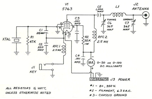
Another single-tube transmitter circuit encountered by amateur radio newcomers in the 01960s and 01970s was the 5763-based 80- and 40-meter circuit included in the Editors and Engineers paperback books Amateur Radio Construction Projects (1963), Practical Ham Radio Projects (1964), and Easy to Build Ham Radio Projects (1967), all by Charles Caringella, W6NJV. Figure 2 shows its circuit.
|
| Figure 2—Schematic diagram of the one-tube transmitter by Charles Caringella, W6NJV. The design is a "grid-plate" (aperiodic tri-tet) oscillator. The popular Ameco AC-1 beginner's transmitter used a 6V6GT tube in essentially the same circuit. A 6417 tube (12-V 5763) works as well as a 5763 in this circuit with 12.6 V instead of 6.3 V on its heater. The maximum capacitance specified for the LOADING control (365 pF) is too low for use with a 50-Ω antenna system even at 40 meters; a two-365-pF-sections capacitor, with both sections connected in parallel and augmented by a switch-connectable additional fixed capacitance (say, 680 pF) at 80 meters, is recommended instead. |
Things to Do and Not Do with Your W6NJV 5763 Transmitter
Do not use the too-high tuning inductance values specified by the author. The Miniductor-based coils described by Caringella result in tuning inductances of about 17.6 μH at 40 meters and 41.2 μH at 80. One built-in problem with the 40-meter value is that one is barely able to tune the output network to resonance even with the TUNING capacitor at minimum as a result of stray wiring capacitances summing with the TUNING capacitor's minimum capacitance and the output capacitance of the 5763 oscillator tube. A built-in problem with both values is that they are simply much higher than optimum for getting anything like maximum output from a 5763 oscillator operating with 350 V on its plate. At W9BRD I use 10.6 μH at 40 meters and 21.2 μH at 80 meters, which values give 7 W output at 40 and nearly 8 W output at 80 when the transmitter is tuned for maximum output and then slightly detuned below maximum output for best keying. (More capacitance will be needed on both bands at C7, the LOADING control, if this is done.)
Do tune the transmitter for maximum output power—not plate-current dip—and then slightly retune for best keying. Maximizing output at plate-current dip is about tuning an amplifier. An oscillator is an amplifier that supplies its own input signal, the level of which varies with output tuning and loading. As a further complication, best keying quality commonly does not coincide with maximum output in keyed oscillators. Therefore the "dipping and loading for max" tuning approach that's correct for "just an amplifier" is incorrect for optimum tuning of a single-tube-oscillator transmitter.
Do experiment with reducing the value of R1, the 47-kΩ grid resistor, to decrease chirp and yoop. An R1 of 10 or 12 kΩ has worked well in experiments at W9BRD. Depending on the crystal in use, keying may be somewhat "lighter" as a result of this modification—the oscillator will take a bit longer to start oscillating on key down and will stop oscillating a little sooner on key up—but if you're sending with a straight key while monitoring your own transmitted signal, you'll compensate for this condition automatically. (Thanks to Monte Allen, W9BMW, for this lower-value-grid-1-resistor tip, which I discovered in the page at https://www.qsl.net/wb1gfh/ameco1.html. It entirely supersedes other commonly applied techniques to reduce chirp in single-tube-crystal-oscillator transmitters, including adjusting feedback by changing values in the circuit's Colpitts voltage divider and regulating the voltage supplied to the oscillator-tube screen [grid 2].)
Do connect a 150-kΩ resistor (or a lower value, as necessary) across the keying line to keep the KEY UP voltage between the oscillator tube cathode and common to a value that does not endanger the tube's heater-cathode insulation. Assuming that the oscillator grid-1 resistor is connected between grid 1 and common—as is so in all of the schematic diagrams in this page—the open-circuit (KEY UP) voltage seen during cathode keying is the positive equivalent of the tube's cutoff bias. The Ameco AC-1 and W6NJV oscillator circuits shown in Figures 1 and 2 in this page use just series voltage-dropping resistors between grid 2 (the screen) of their oscillator tubes and the high-voltage supply. Because a voltage-dropping resistor can only reduce voltage if current flows through it and because there is essentially no current flow through the screen resistor in the KEY UP condition, grid 2 of the oscillator tubes floats nearly up to the high-voltage-supply level when the tube is not conducting. This causes the tube's cutoff voltage to soar far above what it would be were the grid 2 voltage held more constant (as with a voltage-regulator tube or resistive voltage divider), endangering the tube's heater-cathode insulation (which is commonly rated to withstand no more than 100 V dc). Connecting a high-value resistor between cathode and common allows the tube to conduct a very small current, resulting in enough voltage drop through the screen voltage-dropping resistor to reduce the screen voltage to a level that keeps the tube's open-circuit cathode voltage to a safe value. For example, with a 6DS5 operating in the AC-1 (Figure 1) circuit with a 15-kΩ screen dropper and a high-voltage supply of 325 V KEY UP, the oscillator tube's KEY UP cathode voltage was 106 without 150 kΩ between the keying line and common, and 35 V with the protection resistor in place. 35 V across 150 kΩ equates to a current flow of just 0.2 mA through the tube—not nearly enough to allow the tube to oscillate with the key up.
Do connect a 1-μF plastic-film capacitor (100 V rating or higher) in series with 330 Ω across the keying line to eliminate the strong click on key up (BREAK).
Do not double or triple the crystal frequency in the oscillator output. The W6NJV transmitter's C-L-C pi output network is a peaked low-pass filter. Use of "subharmonic" crystals—say, a 3.5-MHz crystal for 7-MHz output— can therefore result in significant subharmonic energy reaching the antenna system. This is especially FCC-hazardous when unwanted outputs lie outside the ham bands, as would occur when using a 5.068-MHz crystal for output at 10.136 MHz, and especially hazardous if the antenna system is multibanded with traps or paralleled dipoles and does not involve the use of a tuned matching network.
Do use a 20-W power-supply bleeder resistance instead of the 10-W resistance specified in the 5763 transmitter's accompanying power supply circuit. Even at the power supply's stated key-down voltage of 350, the 10-kΩ, 10-watt part specified by Caringella will dissipate over 12 watts (350 squared divided by 10,000). In practice, the bleeder will dissipate even more power most of the time, because with the transmitter not drawing current (during receiving periods), the output voltage of the power supply will be significantly higher than 350.
Do use an attenuator and low-power-capable reflectometer during tuneup as described in Using an Attenuator for Transmitter–Antenna Isolation During Tuneup, below.
Single-Tube-Oscillator Transmitter Challenges
Aside from its low power output (commonly 10 watts or less), the single-tube-oscillator transmitter could be difficult to adjust for good Morse code keying (if it could be adjusted for good keying at all). Poor keying (sluggish startup and/or chirp or yoop—frequency shift at key down) was only one of its hazards, as a few published comments from its heyday reveal:
The problem of an adequate crystal-controlled transmitter for the newcomer who wishes to come on the air for the first time on c.w. has never been very effectively solved for the amateur who has but a small amount of capital to invest in the first rig. The majority of the beginners now coming on the air use some type of a keyed crystal oscillator coupled directly to the antenna system. We all well know the results of this kind of operation. If the crystal is anything but the very best and most active type, the arrangement is capable of almost no usable power output. If the crystal happens to be an especially active one, it will be possible to obtain a respectable amount of power output but bad keying chirps are likely to be present, dots are very often not present if rapid keying is used, or the rig may frequently become temperamental after having lain idle for a few hours or days and refuse to key at all until it is retuned.
Then, if the crystal does operate well and key cleanly, there is always the temptation to raise the plate voltage to increase the power output. This may be fine until the antenna accidently or intentionally becomes uncoupled some fine day with the result that we will usually be in the immediate market for another crystal "as close as possible to the frequency of the last one."—Jack Rothman, W6KFQ, "The Newcomer's Special," Radio, October 01938, pages 38–40 and 66.
The usual beginner's transmitter is built around a single tube, following the premise that more than one stage will make the first step too complicated or too expensive. The frequent result is a transmitter whose coupling to the antenna circuit is critical in adjustment for a compromise between maximum output and reliable, chirp-free keying. To make matters worse, an attempt is usually made to make up for the lack of additional power stages by running the oscillator at high-power input, incurring the danger of crystal fracture as well. Almost everyone who has had experience with high-power oscillators eventually comes around to the oft-voiced conclusion that more troubles would be avoided if the oscillator, be it crystal or self-controlled, is treated as a frequency-control unit with power output of decidedly secondary importance.—Don Mix, W1TS, "A Fool-Proof Rig for 80 and 40 meters," QST, June 01941, pages 20–23.
If you've ever juggled both a single-tube transmitter and an antenna, you'll know what this is all about before we begin. But if you haven't, and are searching for something "simple," look before you leap! Yes, those single-tube 6L6 rigs look awfully simple on paper. And they are just as simple to build. If you've ever operated one, however, you know that simplicity ends right there. Oscillators have a way of misbehaving when coupled to an antenna, and experience has shown that the only way to eliminate all possibility of trouble is to isolate the oscillator from the antenna.—Richard M. Smith, W1FTX, "A Beginner's CW Transmitter," QST, May 01948, pages 25–30.
The keying of an oscillator is something to be avoided if you want to have a signal free from "yoops" and "chirps." Unfortunately, however, the oscillator must be keyed for break-in operation if you want to work near your own frequency, which seems to be the only way to work anyone these days. Most crystal oscillators do not key well unles care is exercised in adjusting their tuning. The Tri-tet and grid-plate circuits key well without critical adjustment as long as the output circuit is tuned to a harmonic of the crystal frequency. However, most crystal oscillators in 3.5-Mc. transmitters are being operating at the crystal fundamental frequency and under this condition the regenerative circuits have little advantage, so far as keying is concerned, over the simple triode or tetrode circuits unless a very well-screened tube is used. The usual 6V6 and 6L6 do not fall into this category. With any of these circuits, oscillation ceases or is erratic whenever the plate is tuned near resonance where best output is obtained. To obtain good keying characteristics at the fundamental, the plate circuit must be tuned so far off resonance on the low-capacitance side that the useful output from doubling oscillators is often less at the fundamental than at the second harmonic.
To adjust such a circuit for clean keying, it isn't sufficient to hold the key closed and tune the plate tank to the point on the edge of oscillation where the output is greatest. With such an adjustment a loaded oscillator seldom will key well, if starts again at all, once the key is opened. The only way to adjust the oscillator tuning is to listen to the signal while it is being keyed as the plate circuit is tuned to the point where the circuit keys well, regardless of the output. It is impossible to determine this point through meter readings. Depending upon how heavily the oscillator is loaded, it may be necessary to detune the plate circuit considerably to avoid chirps.—Donald Mix, W1TS, "Unstable Signals," QST, August 01946, pages 25–30, 126.
Short List of Single-Tube-Oscillator-Transmitter Issues
The operating frequency of an oscillator is affected by loading. As the output tuning of a crystal oscillator is adjusted, its frequency shifts. This occurs as a result of multiple aspects of oscillator physics.
Output-power variation with loading—including variation to the extreme of no output, as can happen when heavy loading reduces feedback below the point required to sustain oscillation—can seemingly make adjustment of antenna matching difficult to impossible. (I write seemingly because use of an attenuator and low-power-capable reflectometer can solve this problem as described in Using an Attenuator for Transmitter–Antenna Isolation During Tuneup, below.) An oscillator is an amplifier that supplies its own driving signal, so diverting too much of an oscillator's output power to its load (a dummy antenna or actual antenna system) can stop oscillation. Related to, and simultaneous with, this, adjusting an oscillator's output tuning can disrupt the input v output phase relationship such that the positive feedback necessary for oscillation is unavailable.
Limited options are available for keying waveshaping. As a result of radio physics, the more rapidly an on-off-keyed signal rises from zero output to maximum (and/or the more rapidly a signal falls from maximum to zero, the more overall space that signal will take in the radio spectrum. We therefore seek to make signal rise and fall times no faster than that necessary for solid communication. A signal that transitions between zero and maximum too rapidly sounds "clicky" on the air; we say that such a signal suffers from key clicks. The physics of crystal oscillators, and the electromechancal characteristics of individual crystals, are sufficiently variable that the keying waveshaping measures that work well in setting amplifier rise and fall time commonly do not work well with crystal oscillators.
In crystal-controlled single-tube transmitters, signal quality (frequency stability and keying waveshaping) may vary with frequency multiplication and with the particular crystal used. See the preceding item. A signal-quality aspect unrelated to measures taken to control signal rise and fall times is that today's relatively physically tiny "HC-49" and smaller crystals (compared to their much larger counterparts of the 01930s through 01960s) cannot handle the RF feedback levels commonly encountered in classical single-tube-crystal-oscillator designs without physically warping enough to cause intractible yoop and chirp.
In crystal-controlled single-tube transmitters, output power may vary with the particular crystal used. Some crystals are more active than others.
In non-tri-tet crystal oscillators, loss or drastic reduction of output loading may destroy the crystal. Ensuring that this cannot happen when the antenna is intentionally disconnected from the transmitter—such as may be true when receiving incoming signals—requires either that the transmitter be connected to a dummy antenna or have its keying disabled during receiving periods.
Running the oscillator at less than full power for spotting—simultaneously listening to your own transmitted signal alongside other, incoming signals—is difficult.
The c.w. man on 80 meters is not a dx man, at least for the moment, and is more concerned with operating ease and efficiency than with anything else. He usually goes up on 80 to work U.S.N.R. or A.R.R.S. drills, to keep skeds on traffic nets on spot frequencies, or to just plain chew the fat, without being smothered with QRM or dropped like a hot potato after reports are exchanged.
Now anybody who has done much operating on 80-meter c.w. knows that 25 to 50 watts in an antenna worthy of the name will do just about as good a job as a kilowatt if there isn't somebody else with more power smack on your frequency. For this reason many c.w. amateurs do not attempt to put their regular transmitter on 80 meters but instead use a keyed crystal oscillator which is left all tuned up "sitting in the corner" and ready to go at a moment's notice.—W. W. Smith, W6BCX, "Strictly 80 Meters," Radio, January 01941, pages 90–93 and 162.
Using an Attenuator for Transmitter–Antenna Isolation During Tuneup
Especially if you seek to use a single-tube-oscillator transmitter to drive an antenna through an antenna tuner, adjusting a single-tube oscillator for best keying and output—or even getting it to oscillate at all—can appear to be impossible: You can't adjust the tuner in the absence of transmitter output, but the transmitter may not be adjustable to work at all unless it's feeding something close to a 50-Ω load!
The solution to this problem is straightforward: Insert a designed-for-50-Ω 6-dB attenuator between transmitter and tuner, with your system SWR meter/reflectometer connected between attenuator and tuner. The impedance-constrained load provided by the attenuator–tuner–antenna combination will allow you to make the transmitter work even if the load presented by the antenna tuner/antenna is far from 50 Ω, resistive.
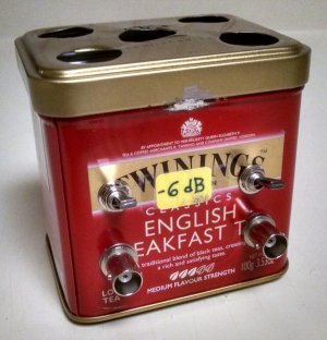
You'll need a 6-dB pi attenuator capable of safely dissipating at least your transmitter's maximum output power. It's easy to build one in a metal can, with each of the three resistances in the pi consisting of groups of 2- or 3-watt metal-oxide-film power resistors in parallel (Figure 3). Equip the attenuator with switches—miniature toggles are fine—so you can easily switch it into and out of the line at will.
|
| Figure 3—6-dB transmit "pi" attenuator built into a Twinings tea tin. Its power-handling capability is such that it can also provide "instant QRP" when used with a 20-W-output transmitter. Holes on top and bottom provide convective cooling when the attenuator operates at tens-of-watts input levels; stick-on feet on the bottom provide clearance for airflow. |
Because the power output of a 6-dB attenuator is one-fourth that applied to its input, you'll also need an SWR meter/reflectometer that's capable of full-scale forward-power indication at 1/4 of your transmitter's full output power. If you don't already have such a meter, I recommend the easy-to-build, needs-no-tricky-calibration hybrid bridge designed by David Stockton, G4ZNQ (https://www.sm7ucz.se/Meters/Stockton_pwr_meter.pdf).
You'll also need a 50-Ω dummy antenna capable of handling your transmitter's maximum output power. For maximum ease of use, build in switching so you can switch between the dummy antenna and the antenna tuner/antenna system at will.
A means of monitoring—actually listening to, in real time—your transmitted signal is essential.
Assuming that you have the above pieces in place and ready, I recommend the following tuning procedure:
1 Connect the transmitter to the dummy antenna and adjust it for your favorite combination of acceptable output power and acceptable keying. Adjust the SWR meter/reflectometer for full-scale FORWARD indication at this point, and note the meter-sensitivity-control setting so you can return to it later.
2 Switch in the 6-dB attenuator, and then readjust the SWR/meter/reflectometer for full-scale FORWARD indication.
3 Connect the attenuator output to the antenna tuner/antenna system instead of the dummy antenna, and then adjust the antenna system for minimum reflected power.
4 Switch out the 6-dB attenuator, and then reset the sensitivity of your SWR meter/reflectometer to the lower-sensitivity setting noted at Step 1.
5 Make any final tweaks to the transmitter settings. Do not adjust the antenna tuner at this point.
The above process will keep you clear of the frustration of having a transmitter than won't oscillate reliably as you make antenna-tuner adjustments. As a secondary but nonetheless valuable benefit, the transmitter settings that give good power output and keying should require no more than slight readjustment, if any, when you switch out the attenuator.
Chambers's "A Compact Portable-Emergency Transmitter" (April 01941 QST)
This transmitter consists of a grid-plate (aperiodic-anode tri-tet) oscillator circuit coupled to the antenna via a pi impedance-transformation network (Figure 4).
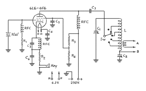 |
| Figure 4—Unusually for a pre-World War 2 circuit, Vern Chambers's beginner's/emergency transmitter, a cathode-keyed Colpitts crystal oscillator, used a pi output network for coupling power to its antenna system. (Ignore the output link; that was optional.) The capacitor-inductor-capacitor pi network became standard after the war because the advent of TV and TVI (ham interference to TV) made its built-in low-pass-filtering action valuable in suppressing harmonics, and because coaxial cable became much more widely used as an antenna feedline. The use of cathode bias (developed by voltage drop across R2), uncommon in an era when hams strove to get every last watt out of a circuit, is a good practice because it protects the tube from overload when it's keyed but fails to oscillate. (C6 is unnecessary, by the way; the RF-ground end of C3 can be connected directly to chassis. The capacitive voltage divider that makes this oscillator a Colpitts comprises the tube's grid-to-cathode capacity and C3.) This revised drawing corrects the original schematic's misconnected screen–R3–R4 arrangement, in which R4 was connected directly across the +B line. With 250 volts on the tube plate, even with a 6L6 in use this circuit would have put out no more than 5 watts or so—the output power level we now refer to as QRP. |
Some Results of My Experiments with the Chambers Transmitter Circuit
Note: The keying-quality characterizations presented below, the result of experiments done circa 02010, assume a classically high value (on the order of 47 kΩ) for control-grid resistance R1. Quite likely the "Do experiment with the value of R1" instructions presented above for the Ameco AC-1 and W6NJV transmitters would materially improve keying-quality characterizations other than "excellent." If you experiment with the "reduce the value of R1" technique with the Chambers circuit, do also remove (replace with a short circuit) the RF choke (RFC) shown in series with R1 in Figure 4. This is necessary because the efficacy of reducing the value of R1 assumes that the reduced grid-resistor value is operative at RF and dc.
Unshielded 12V6GT with 105 V on screen: 1.3 Wo (watts output) at 7.01 MHz, excellent keying.
Unshielded 12V6GT with 150 V on screen: 4.5 Wo at 80 meters, excellent keying.
1631 (12-V-heater metal 6L6, shell grounded to chassis) with 105 V on screen: 2.4 Wo at 7.01 MHz, excellent keying.
1631 with 105 V on screen: 4.3 to 4.5 Wo at 80 meters, excellent keying.
1631 with 213 V on screen: 9.0 to 9.3 Wo at 80 meters, excellent keying.
1631 with 213 V on screen: 6.9 Wo at 7.01 MHz, good keying (slight yoop detectable).
1631 with 150 V on screen: 3.7 Wo at 7.01 MHz, good keying (slight yoop detectable, but less than with 213 V on screen).
1631 with 150 V on screen: 6.0 to 6.2 Wo at 80 meters, excellent keying.
12A6 (shell grounded) with 150 V on screen: 2.7 to 2.8 Wo at 80 meters, excellent keying.
Unshielded 6AK6 with 105 V on screen and 22 pF/100 pF feedback: 1.5 W at 3.52 MHz with 3.52-MHz crystal, excellent keying.
Unshielded 6AK6 with 105 V on screen and 22 pF/100 pF feedback: 0.4 W at 7.04 MHz with 3.52-MHz crystal, excellent keying.
Unshielded 6AK6 with 105 V on screen and 22 pF/100 pF feedback: 0.77 W at 7.12 MHz with 7.12-MHz crystal, good to excellent keying.
Unshielded 6AK6 with 150 V on screen and 22 pF/100 pF feedback: 1.7 W at 3.52 MHz with 3.52-MHz crystal, excellent keying.
Unshielded 6AK6 with 150 V on screen and 22 pF/100 pF feedback: 0.77 W at 7.12 MHz with 7.12-MHz crystal, good keying.
In all cases above, the plate voltage was 360, key down, and screen voltage was VR-tube-regulated. The plate inductor used was that of the Mighty Midget. The RF-voltmeter detector diode was a 1N4148 (silicon). 80-meter crystals were FT-171Bs; the 40-meter crystal was housed in a large, rectangular black bakelite case, likely with a quartz element of a size on par with that of the FT-171Bs. Although the grid-plate circuit can be used for fundamental and harmonic output with some tubes—actually not a good idea because of the low-pass nature of the pi network—with the 1631, 80-meter crystals will not oscillate with the plate tuned to 40 meters, indicating the importance of feedback from the plate circuit in this ostensibly electron-coupled triode-tetrode circuit. (I did not evaluate the usability of 80-meter crystals at 40 meters with the 12V6GT and 12A6.)
Optimization of the output network for each tube type would likely increase power output over the values shown above while maintaining the ratio of the band-to-band output differences for a given tube. Optimization of the feedback capacitor values—in the original Chambers circuit, only the tube's grid-to-cathode capacitance serves as the upper capacitor in the divider—would likely improve output and/or keying, especially at 40 meters.
Additional Single-Tube-Oscillator Experiments, Various Tubes and Circuits
The 17JQ6 Beam Power Tube as a Power Crystal Oscillator
The xJQ6 (6JQ6, 12JQ6, 17JQ6) beam power tube, intended for vertical-deflection-amplifier service, is attractive for RF power oscillator service because it has low grid-plate capacitance (0.32 pF, unshielded, as compared to 0.3 pF for the 5763/6417) and a relatively high-power cathode (its heater operates at 7.56 W [6.3 V at 1.2 A, and so on]), and because its beam-forming plates are not internally connected to its cathode (allowing better decoupling of oscillation feedback from output tuning in triode-tetrode topologies). A curiosity: The xJQ6 includes an integral beam-plates-to-cathode diode intended to regulate the beam-plates-to-cathode differential at about 5 volts, but because beam plates are normally operated at ground potential (negative with respect to the cathode) or wired to the cathode (therefore operating at the same potential as the cathode) in RF oscillator and RF power amplifier service, the integral diode will therefore be inoperative when the xJQ6 is used in most radio-transmitter applications.
In an experimental grid-plate (aperiodic tri-tet) power crystal oscillator at AB2WH, a 17JQ6 produced 6.0 Wo at 80 meters (at 11.8 Wi, for an efficiency of 51%). The circuit used a 22 pF/220 pF feedback divider; 340 ohms of cathode bias resistance; a 22-kilohm grid leak (with no series RF choke); a plate voltage of 360 (key down); and a screen voltage of 150. The output network was a parallel-LC circuit (in ac parallel with dc feed through a 2.5-mH choke) using a 10.6-µH solenoid (17 turns of #24 enameled copper wire, 1.25 inches in diameter, closewound [0.5 inch long]) with output coupling via a 3-turn link series-tuned with an 1100-pF variable capacitor. Up to 13.3 Wo was available with 180 V on the tube's screen and no cathode bias resistance, but keying was slightly to moderately yoopy at this power level. In further experiments at 80 meters with the aperiodic tri-tet at W9VES, a 17JQ6 configured as above but with a pi output network with a 13-µH solenoidal plug-in inductor produced 6 to 6.3 Wo at a screen voltage of 105 and 8 to 8.4 Wo at a screen voltage of 150. Keying was yoop-free in both cases.
Reconfiguring the circuit as a frequency-doubling (3.5-to-7-MHz) tuned-anode tri-tet oscillator (cathode tank, 3.3 µH in parallel with 220 pF; plate output matching, via a pi network based on a 6.5-µH inductor wound on a T130-2 toroidal powdered-iron core) netted 6.2 Wo (3.55-MHz crystal) to 7.8 Wo (3.51-MHz crystal) with good to excellent keying. (In most "good keying" cases, keying could be improved to "excellent" by detuning the output network away from exact second-harmonic resonance.) The screen voltage was 180, the cathode bias resistance was 340 ohms, and the grid leak resistance was 22 kΩ; apparently, a higher screen voltage can be used in this doubling tri-tet configuration [compared to 150 V for acceptably good keying in the grid-plate configuration described above] because the crystal is subjected to relatively little output-to-input feedback when the output circuit is tuned to twice the resonant frequency of the crystal.)
[to be continued...]
| Revised February 1, 02021. | Copyright © 2007–2021 by David Newkirk (david.newkirk@gmail.com. All rights reserved. |
| home |