The Crystalizer: Obtaining Crystal-Oscillator Output at f, f × n, and f ÷ n
A classic amateur radio transmitter topology, the oscillator-amplifier (sometimes called master oscillator, power amplifier, or MOPA), used one tube for frequency control and another for RF power amplification, and in quartz-crystal-controlled form commonly allowed operation on two or more bands with one crystal. Frequency multiplication—generation and selection of harmonics (multiples) of the crystal oscillator's fundamental frequency—was the basis for this. In the earlier days of frequency multiplication, separate stages performed the roles of frequency generator and harmonic multiplier because only triode vacuum tubes were available. The advent of the screen-grid tube (tetrodes, pentodes, and beyond), the embedded screen grid/control grid/cathode triode in which could serve as a triode oscillator at the crystal fundamental while harmonic output was obtained by suitably tuning the plate, made two-tube, three- and four-band oscillator-amplifier transmitters possible by 1933 CE. Nearly all screen-grid oscillators capable of this class of operation are a form of tri-tet, although non-tri-tet variations, such as Frank Jones's harmonic Pierce oscillator, were possible as well.
Seeking to approach the utility of the tri-tet multiband oscillator with transistors, and having achieved excellent results in synthesizing a tetrode with cascode-connected vacuum-tube triodes for regenerative-detector service, I recalled the cascoded-BJTs VCO buffer amplifier described by David Stockton, GM4ZNX, in the Oscillators and Frequency Synthesizers chapter he wrote for the 1995 CE ARRL Handbook for Radio Amateurs and wondered if an oscillator based on cascoded transistors might approach the multiband utility of the tri-tet. Through private correspondence, Wes Hayward, W7ZOI, pointed out that Experimental Methods in RF Design (EMRFD) had included in its Figure 12.47 the cascoded-BJTs variable crystal oscillator (VXO) first described by EMRFD co-author Rick Campbell, KK7B, in "The MicroT2—A Compact Single-Band SSB Transmitter," QST, December 2006, pages 28–33. Rick's goal in developing that design had been highly stable output at the crystal fundamental; its output was obtained through a low-pass pi network that suppressed harmonics. Could that same general topology provide useful output at the second harmonic?
Yes—and the circuit I arrived at (Figure 1), does more: It produces output not only at f and 2f, but also at f/2 through f/6 using the gated-LC-oscillator technique (Figure 2) described in J. A. De Young, W1HHW, "A Frequency-Lock Multi-Vider," QST, September 1935 CE, pages 32 and 33. Figure 3 shows the amplifier circuit I use to bring the Crystalizer output up to a level suitable for driving a vacuum-tube-based crystal oscillator stage.
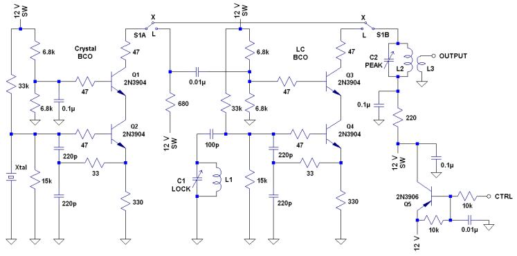 |
| Figure 1—Operating by means of two bipolar junction transistor cascode oscillators (BCOs), this circuit, the Crystalizer, provides output at the crystal fundamental or a harmonic when S1 is set to X, with tuned circuit L2-C2 selecting the appropriate frequency. Output at submultiples (subharmonics) of the crystal fundamental is available when S1 is set to L and tuned circuit L1-C1 is tuned to the appropriate subharmonic. (L2 is 6.6 µH and L3 is 1 µH for output at 3.5 MHz; scale for other bands.) Grounding and ungrounding the CTRL terminal turns the Crystalizer on and off for spotting and transmit-receive-switching purposes. When amateur radio station W9VES operates at 3.56 MHz under crystal frequency control, the Crystalizer generates the driving signal—from a 7.12-MHz crystal. |
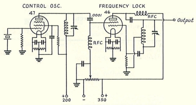 |
| Figure 2—For its frequency-division function, the Crystalizer uses the BJT equivalent of the frequency-locking technique implemented in this circuit, the "Frequency-Lock Multi-Vider" (J. A. De Young, W1HHW, QST, September 1935 CE, pages 32 and 33). Note the use of the 46 dual-grid power amplifier tube—designed for use as a low- or high-µ triode—as a tetrode Hartley oscillator, its outer grid serving as a second control grid. |
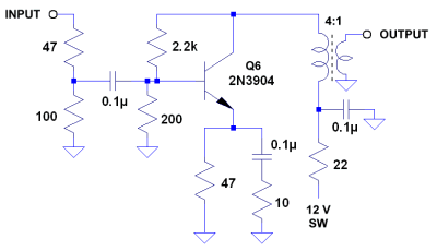 |
| Figure 3—This amplifier increases the signal from the Figure 1 circuit to between 90 mW (doubling) and 110 mW—a level sufficient for driving the cathode of a vacuum-tube crystal oscillator stage. (Circuit from Roger Hayward, KA7EXM, and Wes Hayward, W7ZOI, "The Ugly Weekender Transmitter," QST, August 1981, pages 18–21.) |