Described in pages 54–57 of February 01966 QST by Lewis G. McCoy, W1ICP, the Mighty Midget transmitter (Figure 1) uses a 6GW8 triode-pentode in an oscillator-amplifier design that combines a curious misapplication of oscillator fundamentals with insufficient attention paid to issues of amplifier stability. The result is a transmitter that should not be duplicated and used on the air without considerable circuit modification.
|
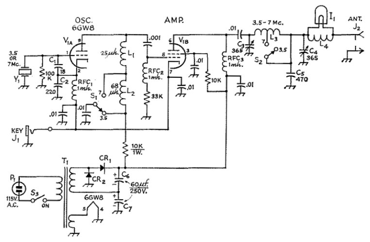
| Figure 1 — Schematic of McCoy's "Mighty Midget" transmitter. That the design's power amplifier (6GW8 pentode) is not neutralized and includes operating-frequency-tuned circuits in its grid and plate circuits renders that stage a tuned-plate, tuned-grid oscillator that—if you're lucky—locks to the frequency of its triode crystal oscillator and stays there. |
The Mighty Midget's troubles begin with its oscillator, a common-anode triode Colpitts circuit that nonetheless operates with its anode held above RF ground by the imprecisely resonant circuit formed by one RF choke (40 meters) or that RF choke plus another choke in series (80 meters) paralleled by the capacitance to ground of the triode anode and pentode grid and their interconnecting wiring. The use of the Colpitts arrangement, the building-in of oscillator-anode parallel resonance, and the use of an RF choke in series with the power amplifier grid-leak resistor—a usage more or less obsolete as of the mid-1950s—suggest that in designing the Mighty Midget, McCoy had worked to avoid the power amplifier underdrive of the Boosted Pierce: Eleven years earlier, beginning on page 36 of October 1955 QST, he had modified an aperiodic-oscillator-based commercial design to overcome exactly that problem by adding oscillator-anode tuning and power-amplifier neutralization in "More Power with the AT-1."
The presence of oscillator anode (amplifier grid) resonance without the addition of amplifier neutralization results in a serious flaw: With its anode and grid tuned to roughly the same frequency by design, the transmitter's high-gain pentode power amplifier is unstable to the point of acting more like a locked oscillator than just an amplifier. Suspecting that this might be true with my version of the Mighty Midget after I encountered hysteresis in its amplifier plate tuning at 40 meters—I couldn't achieve the same output power peak, and maximum output occurred at different settings, when tuning through resonance from above and below resonance—I disconnected the cold end of the oscillator cathode choke from the KEY jack and discovered that the Mighty Midget put out more RF power with its crystal oscillator disabled than with its crystal oscillator connected and operating! Adjusting the amplifier plate tuning across a wide range below, through, and above resonance and back again, I heard a series of grunts and squawks in my receiver as the final amplifier found and rejected varying modes of oscillation, some purer than others. Holding my key down at the circuit's highest power output setting, I discovered a relatively pure but highly frequency-unstable signal at about 7065 kHz. Moving a hand near the oscillator-anode chokes swung the frequency wildly. Keyed on and off, the amplifier-cum-oscillator chirped like the proverbial bird. This is a transmitter suitable for neither beginner nor Novice.
Writing of his own experiences with the Mighty Midget, the PI4RAZ club website administrator—who, if I have inferred from my drillings-down correctly, is Frank Waarsenburg, PA3CNO—confirms the hazardous locked-oscillator nature of its design:
When I increased the anode voltage to 300 V, the fight began. David Newkirk was right. The tuned circuit in the anode of the triode is in the grid circuit of the pentode! I had actually built a crystal-oscillator-synchronized TPTG (tuned plate, tuned grid) oscillator. The transmitter put out more power with the crystal removed than with the crystal in place. (translation from the Dutch by Google and D. Newkirk, W9VES)
At least two options are available for taming the Mighty Midget transmitter. One would be to abandon its triode oscillator, rewiring the oscillator's Colpitts capacitive voltage divider to the grid and cathode of the pentode and moving the triode's cathode RF choke to the cathode of the pentode. This turns the transmitter into an electron-coupled, "grid-plate" pentode oscillator-only design. Keying will be excellent at 80 meters (4.1 W output measured in my test version) and acceptable (2.8 W output) at 40 meters. Figure 2 shows this option.
 |
| Figure 2 — Rewiring the "Mighty Midget" final amplifier as a Colpitts crystal oscillator. The 6GW8 triode is unused. |
The other option is to reconfigure the Mighty Midget as a Boosted Pierce: Rewire the 6GW8 triode as a Pierce oscillator, removing the low-value RF chokes used for oscillator-plate resonance in the original design and moving the oscillator cathode RF choke to the oscillator plate circuit. With this arrangement, output with 350 V on the amplifier plate will be nearly 5 W at 80 meters (excellent keying) and 4 W at 40 meters (acceptable keying [that is, keying with some yoop, which I attribute to crystal heating]). Figure 3 shows oscillator changes for this option.
 |
| Figure 3 — Rewiring the "Mighty Midget" triode as a Pierce crystal oscillator. The 470-kΩ resistor acts as a pull-down to reduce dc voltage across the crystal. For a better-sounding signal, power the crystal oscillator from a regulated source of no more than 150 volts. |
| Revised November 18, 02016 CE. | Copyright © 2007–2016 by David Newkirk (david.newkirk@gmail.com). All rights reserved. |
| home |