Homemade Equipment Pictures 0
The Utility Audio Amplifier/Filter Box
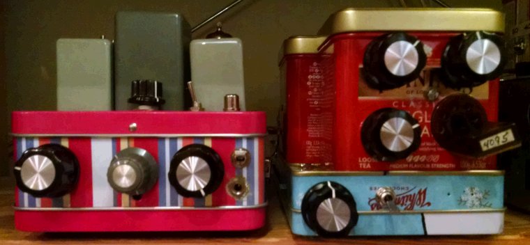 |
| Figure 1—The audio amplifier/filter box and BGCD Regenerodyne receiver on the operating-position shelf at amateur radio W9BRD. The AF amplifier/filter lineup is: 7060 triode cathode follower; switchable AF low-pass filters; 7060 pentode voltage amplifier; and 12A6 or 7701 beam power tube power amplifier. The BGCD receiver lineup is: 12A6 beam power tube/2N7000 MOSFET hybrid mixer; 2N3904 crystal conversion oscillator; 12J5 triode grounded-grid IF buffer; 12A6 regenerative detector centered at 3.023 MHz; and 12J5 audio voltage amplifier. Yes, those are pencil, candy, and tea tins. |
 |
| Figure 2—Front view of the audio amplifier/filter box, via which all homemade, tube-based receivers at W9BRD are amplified to headphones or speaker level. The front-panel rotary controls from left to right are AF GAIN, BANDWIDTH, and POWER AMPLIFIER GAIN; the front-panel toggle turns the rear-panel SPeaker jack on and off. The gray blocks are passive AF low-pass filters, selectable by the gray BANDWIDTH knob. The small knob centered above the front panel allows me to preset a small amount of loss with AF filtering switched out to equalize the box's output between "filtering in" and "filtering out." |
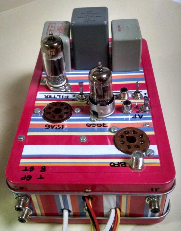 |
| Figure 3—Rear view of the audio amplifier/filter box. The extra octal socket at the lower right, and the BFO and IF jacks, were included to support a receiver topology long abandoned; I'll remove and/or repurpose those parts as necessary. My tentative plan is to install two 7-pin tube sockets in place of that extra octal socket and wire them such that two 6BH6s, one triode-connected, can be plugged in in place of the 7060 triode-pentode. The lower jack on the left, ST, allows injection of sidetone audio for monitoring keying during two-way Morse code operation as W9BRD. |
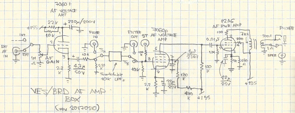 |
| Figure 4—Amplifier/filter box schematic circuit diagram. The 10-kilohm audio filters are UTC/Triad LMI-series or equivalent parts. |