Homemade Equipment Pictures 3
The WR/6AK6s-40 Regenerative Receiver and ZOIDC-40 Direct-Conversion Receiver
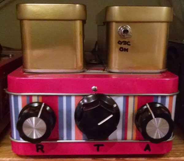 |
| Figure 0—The WR/6AK6s-40 regenerative receiver covers the Morse-code-friendly portion of the 40-meter (7-MHz) amateur radio band. This platform—a pencil tin with Twix "Heritage Tins" affixed, actually houses two receivers: The WR/6AK6s-40 and a solid-state, 40-meter direct-conversion receiver, the ZOIDC-40, based on the discrete-2N3904s Gilbert-cell design presented by Wes Hayward, W7ZOI, in Hayward, Larkin, and Campbell's Experimental Methods in RF Design. From left to right, the receivers' controls are REGENERATION (WR/6AK6s-40), TUNING, and AF GAIN (ZOIDC-40). The utility audio amplifier/filter box brings the WR/6AK6s-40's audio output up to headphones or speaker level. The utility amplifier/filter box can also be used with the ZOIDC-40, but for vacation and casual use the ZOIDC also includes an LM386 audio power amplifier. The OSC ON switch controls a 7120-kHz crystal marker oscillator. |
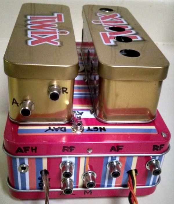 |
| Figure 1—Back-panel view of the WR/6AK6s-40 regenerative and ZOIDC-40 direct-conversion receivers. The NGT/DAY switch controls a 10-dB RF attenuator for the ZOIDC-40, necessary at night to optimize use of the direct-conversion receiver's limited AM-demodulation-resistance dynamic range. The A and R jacks are relics of the experimental addition of a third receiver—a simple two-diode-detector direct-conversion design—to the WR/6AK6s-40|ZOIDC-40 platform. Both receivers have their own RF-input and AF-output jacks; the only jack they share is M, muting, short-circuiting the inner and outer conductors of which quiets the receivers during transmitting periods. |
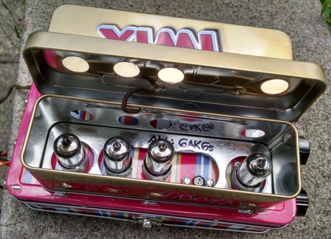 |
| Figure 2—A Twix "Heritage Tin" shields the WR/6AK6s-40's four 6AK6s, of which three are low-mu-triode-connected—two operating in cascode as a synthetic tetrode for the set's Hartley detector, and one operating as a grounded-grid RF buffer amplifier between antenna and detector—and the fourth is pentode-connected for more gain as the set's AF output voltage amplifier. The trimmer capacitor adjusts the upper limit of the set's tuning range, currently about 7105 to 7125 kHz. (The ZOIDC-40 tunes from about 7090 to 7125.) |
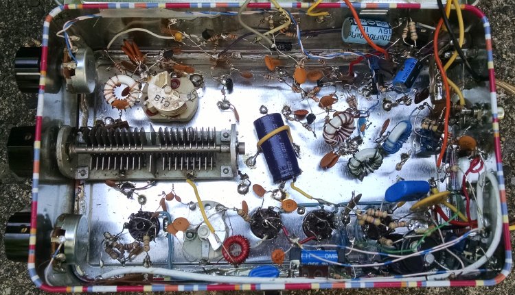 |
| Figure 3—WR/6AK6s-40|ZOIDC-40 main wiring. A two-section tuning capacitor tunes both simultaneously (but only one is used at a time); the tube-based WR/6AK6s-40's wiring is below this capacitor, and (most of) the all-solid-state ZOIDC-40's wiring is above it. The three toroidal coils to the right of the tuning capacitor are part of the ZOIDC-40's input circuitry. |
|
|
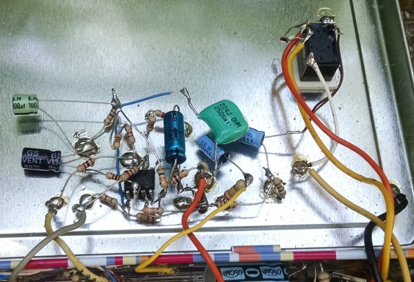
Figure 4—ZOIDC-40 wiring annex. The original ZOIDC-40 circuit applies the differential audio outputs of its discrete-2N3904s Gilbert-cell detector directly to the differential inputs of an LM386 power-amplifier IC without including an AF GAIN control. This two-stage circuitry implements a differential amplifier to facilitate AF gain adjustment and a second AF gain stage to provide "line output" suitable for driving the utility audio amplifier/filter box.
|
[to be continued...]