Homemade Equipment Pictures 1
The BGCD 80-, 40-, and 30-meter Regenerodyne Receiver
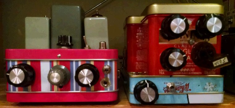 |
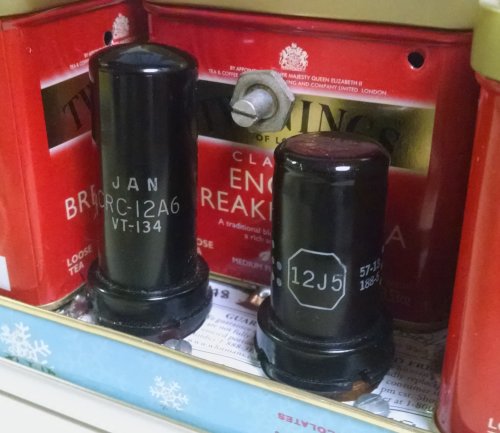
| Figure 1—The audio amplifier/filter box and BGCD Regenerodyne receiver (right) on the operating-position shelf at amateur radio W9BRD. The AF amplifier/filter lineup is: 7060 triode cathode follower; switchable AF low-pass filters; 7060 pentode voltage amplifier; and 12A6 or 7701 beam power tube power amplifier. The BGCD receiver lineup is: 12A6 beam power tube or 6G6G power pentode/2N7000 MOSFET hybrid mixer; 2N3904 crystal conversion oscillator; 12J5 triode grounded-grid IF buffer; 12A6 regenerative detector centered at 3.023 MHz; and 12J5 audio voltage amplifier. Yes, those are pencil, candy, and tea tins. |
The BGCD Regenerodyne Receiver
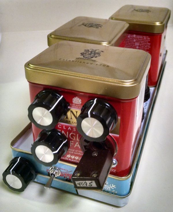 |
| Figure 2—Front view of the BGCD (Byron Goodman-Clinton DeSoto) Regenerodyne receiver for 80, 40, and 30 meters. The front-panel rotary controls are, from lower left to upper right, TUNING, RF PEAK, RF ATTENUATION, and REGENERATION. The toggle switches additional capacitance across the TUNING control for a total IF tuning range of about ±4 kHz around 3.023 MHz. The BGCD is the evolutionary result of my experiments with the 6A8–6K7–6A8–6F6 superheterodyne receiver described by Goodman and DeSoto in "A Unit-Style Portable Station," August 01937 QST. (Since these pictures were taken, the toggle switch has been removed and replaced—a bit further to the right than the toggle—with a second tuning capacitor, giving FAST TUNING and SLOW TUNING capability ±10 kHz from IF center.) |
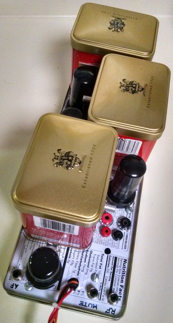 |
| Figure 3—Rear view of the BGCD Regenerodyne receiver. The 12J5 audio amplifier (left) and 12A6 detector tubes are shown. Like other tube-based homemade receivers at W9BRD, the BGCD plugs into the utility audio amplifier/filter box for power and further audio amplification up to the headphones and speaker levels. Shorting to chassis the center conductor of the MUTE jack almost, but not completely, silences the receiver during transmitting periods to allow high-quality monitoring of the transmitted signal. |
 |
| Figure 4—Plan view of the BGCD Regenerodyne receiver, showing the contents of the mixer/oscillator (left), IF, and detector-tuned-circuit cans. |
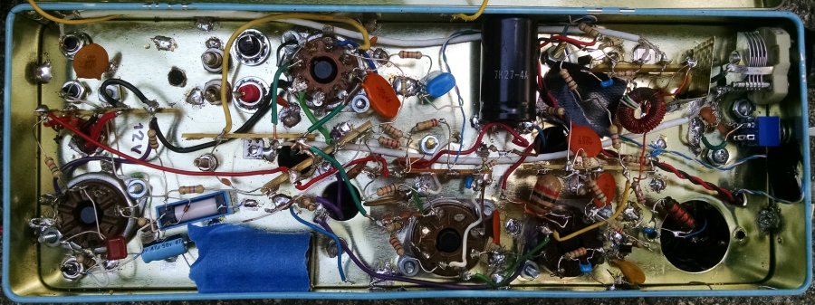 |
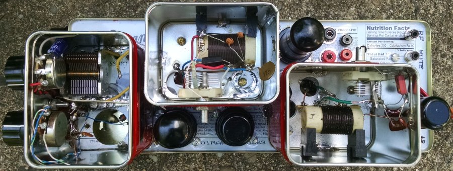
| Figure 5—BGCD under-chassis wiring. Making ground connections to the candy tin is easy: Just scrape the yellow coating down to bare metal and solder. Coaxial cable (white) connects the front-panel TUNING control to the detector tuned circuit (third tea tin from the front!) and also connects the mixer-tuned-circuit link to the ANTENNA jack. |
 |
| Figure 6—The BGCD's mixer, a 12A6 in this photo, and 12J5 IF buffer amplifier tubes in place. The slotted shaft adjusts the mixer plate tuning. Holes in the cans allowed connection to double-ended tubes early in development of the receiver. The 12A6 is teamed with a 2N7000 MOSFET switch driven by a 2N3904 BJT crystal oscillator to perform the frequency-changing function. Types 6G6G (octal 6AK6) and 12A5 have also been tried as mixer tubes in the BGCD with good results; a triode-wired 12SK7 currently serves as the IF buffer. |