Quartz frequency-control crystals in HC-49 cases (rightmost two crystals in Figure 1) are readily and inexpensively available at popular amateur radio frequencies. For those who experiment with vacuum-tube-based transmitters, however, HC-49 crystals represent the challenge of being far too physically tiny and RF-voltage-and-power-intolerant for safe use in classical tube-transmitter circuits. This page presents multiple tube-transmitter circuits that use HC-49 crystals safely while producing modern-quality signals.
|
|
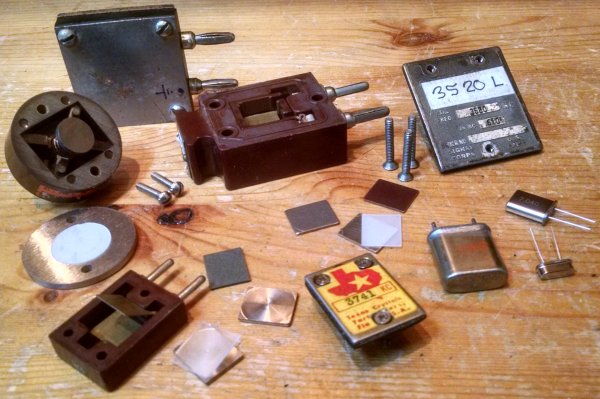
| Figure 1—The physical size of quartz-crystal slices used for oscillator frequency control have progressed from the large (upper left, pre World War 2) to the tiny (current HC-49-cased parts, two rightmost crystals in the picture). To keep them safe and the signals produced by them frequency-stable, today's tiny crystals cannot be used at the circuit power levels at which vintage larger crystals operated in yesteryear's vacuum-tube-oscillator circuits. |
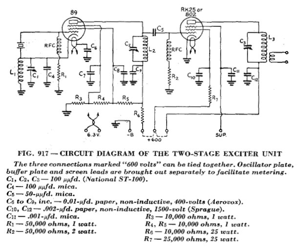
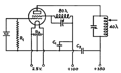
Figure 2 shows what I consider to be the first modern two-stage transmitter design to have been published in QST magazine—in ARRL's The Radio Amateur's Handbook of 1936! Although various details in that design would change over the next 40ish years—different in-vogue oscillator circuits would come and go, for instance—we still find new variations published as late as 1970. The design is basic: A power crystal oscillator/frequency multiplier generates the signal, putting out enough enough RF voltage (at a low power level) to drive an amplifier stage operating in class C. Generally, both stages were on-off-keyed to generate code, although some designs included switching to keep the oscillator ON continuously during transmissions for better signal quality. Depending on the particular design, the stability of supply voltages, and the crystal and crystal-frequency involved, the signal quality with variations on Figure 2 could be excellent to poor.
|
| Figure 2—This two-stage transmitter design from the ARRL's 1936 The Radio Amateur's Handbook would evolve only slightly over the 40ish-year lifespan of the circuit pattern it introduced. Because its oscillator/multiplier stage had to operate at power levels high enough to drive its amplifier into class C, this and other two-stage designs subjected the crystal to voltage and current levels high enough to destroy modern, physically tiny HC-49-cased parts. |
Part of the reason for the "excellent to poor" signal-quality characterization in the previous paragraph is that the crystal type generally in use varied over the life of the two-stage circuit. In 1936, the crystals commonly used were 3/4 to 1 inch across; some holder designs for such even used the metal top plate of the holder as both electrode and heat sink. After World War 2, crystals in FT-243 holders (the 3741-kHz crystal in Figure 1) came into common use through war surplus. Beginning in the 1950s, the HC-6 metal-can crystal holder, as part of which packaging electrode metal was deposited directly on the crystal, became popular. This gradual reduction in crystal size was offset by operating the crystal oscillator stage at lower power and by the use of oscillator tubes with better internal screening (video-amplifier pentodes as opposed to triodes or AF-power-amplifier pentodes) as the lifetime of the two-stage transmitter progressed.
In contrast to this, HC-49s are so fragile and power/voltage intolerant that if we want a transmitter that both doesn't endanger them and also sounds modern—absolutely no yoop or chirp—we need at least three transmitter stages to operate HC-49s at sufficiently lower power while still using a tens-of-watts-output class C tube amplifier at the transmitter output. To keep signal quality high, an HC-49 vacuum-tube oscillator is not keyed ON and OFF for Morse code as in olden times; rather, it's turned ON at the beginning of each transmission and OFF at transmission's end.
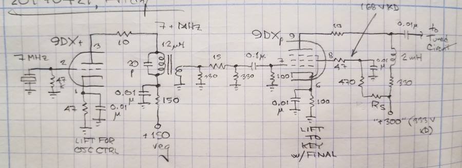
My first HC-49-friendly experiments involved the oscillator-driver circuit I generally refer to as the 9DX (Figure 3) because it uses a tube from the 9DX-based triode/video-power-pentode series developed for television use. The Miller oscillator topology—tuned-plate, crystal-grid—is used, with the oscillator plate fixed-tuned intentionally and significantly above the crystal resonance at a compromise between sufficient output and low crystal stress. Although the oscillator plate-supply voltage indicated in Figure 2 (150) did work without producing crystal yoop or chirp, lower VR-tube-regulated levels—75 or 105/108 V—are preferable.
|
| Figure 3—Schematic diagram of the 9DX oscillator-driver. Frequency pushing as a result of feedback between the plate and grid of the 9DX pentode made me investigate circuits that afford better isolation. The plate circuit of the Miller oscillator is fixed-tuned well on the high side of crystal resonance—no closer to the crystal fundamental than is necessary to provide sufficient drive to the pentode. |
Even with the triode plate tuning and plate voltage levels kept low enough to disallow chirp and yoop, oscillator frequency shift—not apparent as classical chirp or yoop, but rather as a static shift that increases as the pentode output is increased—becomes noticeable at higher output levels from the composite circuit. At first I ascribed this to intra-tube coupling between the 9DX triode and pentode, but experiments show that it occurs even with entirely separate triodes and pentodes. I therefore attribute the effect to frequency pushing that occurs as out-of-phase RF is coupled back to the oscillator through the grid-plate capacitance of the unneutralized pentode. The pi-attenuator pad between oscillator and amplifier in Figure 2 somewhat works against this tendency in addition to providing a more constant load for the oscillator as the pentode is keyed on and off. If in your application you can tolerate the pushing—which does not result in chirp or yoop as the pentode is keyed on and off—the Figure 2 circuit is an acceptable oscillator-driver for an HC-49-crystal-based three-stage tube transmitter, especially at 7.3 MHz and below.
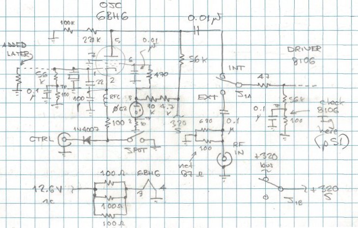
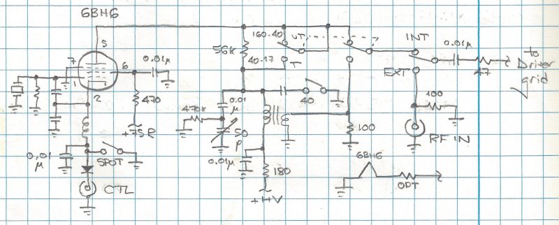
Using a receiving-class RF pentode (Figure 4) has so far given the best and simplest all-around results with HC-49 crystals, however. The 320-kΩ resistance from the 6BH6 plate to common is just there to pull the KEY UP voltage down a bit in my application; it can be omitted if the KEY UP plate supply for the 6BH6 is 300 V or less.
|
| Figure 4—Schematic diagram of an HC-49-crystal-friendly vacuum-tube oscillator, currently the best overall option presented in this page for HC-49-friendly vacuum-tube oscillators. Many small-signal pentodes intended for RF-amplifier use will work; what's especially important is that the tube used should have low grid-plate capacitance (preferably less than 0.01 pF, although the 7054/8077 [specified grid-plate C of 0.065 pF] has also worked well) and that its suppressor grid (grid 3) should be brought out to a separate pin instead of being internally connected to its cathode. The "ADDED LATER" label indicates the oscillator-grid-resistor-reduction modification I subsequently did to further reduce crystal stress as described by Monte Allen, W9BMW, in the Ameco AC-1 transmitter page at https://www.qsl.net/wb1gfh/ameco1.html; the oscillator is sufficiently easy on HC-49 crystals without the W9BMW fix, however. |
Four key features of this oscillator:
| • | It's not keyed ON and OFF for Morse code. |
| • | The oscillator tube has a separate Grid 3 (suppressor grid) connection, which is connected directly to common for better intra-tube shielding. |
| • | The oscillator screen is powered by no more than 108 V, regulated. |
| • | The oscillator plate circuit is untuned to minimize the RF voltage level at the plate, which reduces how much output signal is available to leak back to the grid and cathode. The absence of a tuned circuit between the oscillator and the high-gain video-pentode amplifier it drives also disallows that amplifier to operate as a locked tuned-plate, tuned-grid oscillator. Tubes other than the 6BH6, such as the 6AU6 and 6BA6, will work; a 7054 (with screen at 75 V regulated); the pentode section of a 6BY8 (actually a 6AU6); and the pentode section of a 6AZ8 triode-pentode have also worked in the circuit. Grid 3 of the oscillator must be at RF common for maximum I/O isolation within the oscillator tube. (Grid 3 of the 6AZ8 pentode is connected to one of the tube's heater pins [pin 5], allowing it to be grounded for RF and dc.) |
Shunt capacitance to common from the oscillator plate into the driver grid disallows use of the Figure 4 circuit at at the 20-meter and higher-frequency amateur radio bands. For operation at 14 and 18 MHz, and more drive overhead at 10 MHz, the combination oscillator circuit of Figure 5) can be used. In its TUNED position, the TUNED/UNTUNED switch in Figure 5 switches in oscillator-plate tuning and reconfigures the driver-tube grid circuit to take low-impedance drive from a link winding on the driver-plate tuned-circuit coil. Keeping the driver grid impedance low for RF disallows that stage from acting as a tuned-plate, tuned-grid oscillator; otherwise, the driver would have to be neutralized to avoid oscillation. The internal/external drive switching also shown in Figure 4 is optional; it allows introduction of drive from a low-Z external source.)
|
| Figure 5—Schematic diagram of the combination (tuned/untuned) oscillator. The TUNED mode (T) serves to produce useful output at frequencies at which shunt capacitance to common disallows full driver excitation—generally, at 10.1 MHz and above; keeping the impedance of the driver grid low for RF keeps the driver from operating as a tuned-plate, tuned-grid oscillator in the absence of neutralization. The driver grid is assumed to be loaded by high resistance (47 to 100 kΩ, not shown in this drawing). |
Some frequency variation with plate tuning occurs in the Figure 5 circuit's TUNED mode as tuning is adjusted around and through the crystal frequency, but this shift is static once tuning is set, and no yoop or chirp occurs at oscillator turn-on. Although intrastage-distortion-based frequency multiplication is generally to be avoided in modern transmitters for reasons of spectrum purity, in its TUNED mode the combination oscillator can be used to produce drive from f/2 crystals with reduced concerns about spurious f/2 transmitter output due to subhamonic rejection by the selectivity of the tuned oscillator plate circuit. I've used the TUNED mode for this purpose with crystals at 3.5 MHz for 40-meter operation and 5.06 MHz for 30-meter operation. Oscillator frequency shift with plate tuning is minimum to absent in f/2 operation.
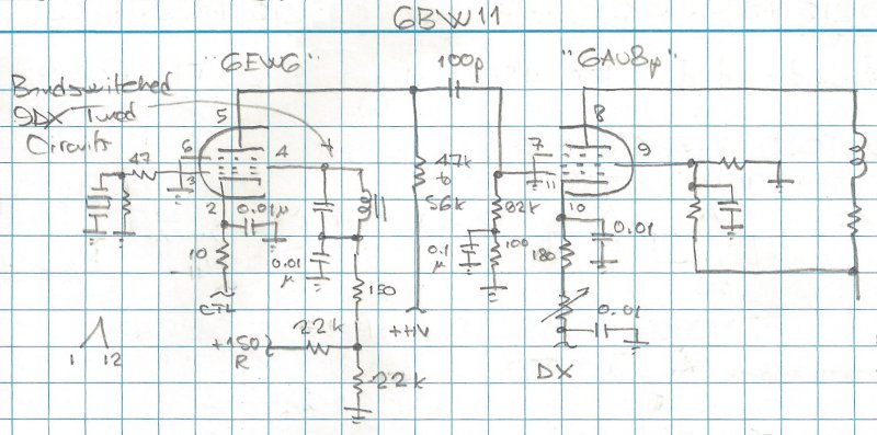
A variation on the pentode-oscillator circuit that also works well is the original "tri-tet"—triode-tetrode—crystal oscillator (Figure 6, first described in December 1932 QST by William P. Durkin, W2DHM), in which the cathode/control grid/screen grid triode embedded within a screen-grid tetrode or pentode tube serves as the oscillator, and the plate circuit of the tube serves mainly as an output coupling element. Figure 7 shows my version of the circuit, in which the cathode, control grid and screen serve as a Miller oscillator as in the 9DX arrangement of Figure 3. This circuit, which has worked well at 3.5 and 7 MHz at W9BRD using a dissimilar-pentodes Compactron (6BW11) with the oscillator screen operating at about 75 V dc, does involve the complication of a fixed-tuned screen tank circuit for each band covered. As with the 9DX oscillator/driver described in Figure 3, the fixed-tuned oscillator tank is tuned well on the high side of crystal resonance, no closer to the crystal fundamental than is necessary to provide sufficient drive to the following stage.
|
| Figure 6—Schematic diagram of the original tri-tet (triode-tetrode) crystal oscillator described in 1932 QST by William P. Durkin, W2DHM. |
|
| Figure 7—Schematic diagram of the HC-49-crystal-friendly Durkin tri-tet and driver. The fixed-tuned circuit is tuned well on the high side of the crystal fundamental as described in the text. Separate pentodes—a small-signal receiving pentode for the oscillator, a video-amplifier pentode for the driver—would work instead of the 6BW11 Compactron tube shown. |
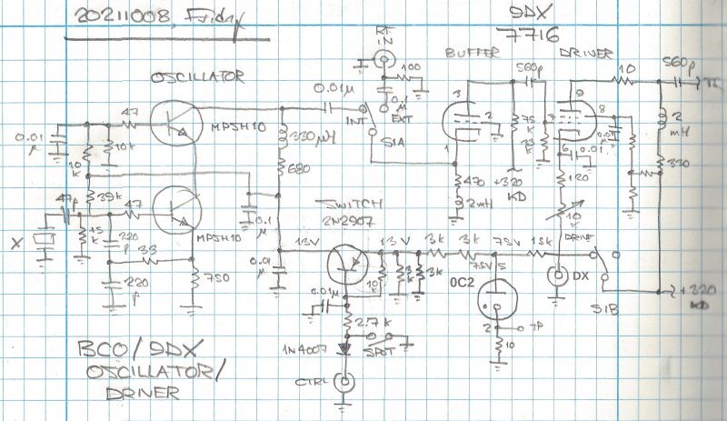
Those not adverse to mixing transistors and tubes may be interested in Figure 8, a hybrid oscillator-buffer-driver that can also drive a TV-horizontal-sweep-tube class C final amplifier to several tens of watts of output. The two bipolar junction transistors (BJTs) form a tetrode oscillator that affords more input/output isolation than a single BJT. (2N3904, 2N2222, 2N4401, and other common BJTs would work as well as the MPSH10s shown.) The triode of the 7716 triode-pentode, a 9DX-based tube, serves as a grounded-grid buffer amplifier that combines voltage gain with good I/O buffering by means of its grounded grid. (Any 9DX-based tube with a "5 watt" pentode can work in this circuit.)
|
| Figure 8—Schematic diagram of the hybrid bipolar-junction-transistor cascode oscillator and 9DX buffer amplifier/driver. The BCO can drive the pentode driver directly, but because the frequency-pushing effect noted with the 9DX oscillator/driver (see Figure 3 and its supporting text) also occurs with with the BCO, additional buffering is needed. This is supplied by the electrostatic shielding afforded by the grounded grid of the 9DX triode. (The 2-mH choke in the triode cathode can be dispensed with; it was included during drive-optimization experiments but does not materially increase drive to the pentode control grid.) The pentode is cathode-keyed via the DX line; the power amplifier it drives is also cathode-keyed. The 0C2-regulated 75-V-to-13-V feed to the oscillator is a holdover associated with the vacuum-tube oscillator replaced by the BJTs; if a 12- to 14-V dc supply is available, you can use that and dispense with the voltage-regulator tube. |
The hybrid circuit is in regular use at W9BRD and, like the pentode circuit of Figure 4, works fine at 80, 40, and 30 meters. (As it would on 160.) At 20 meters and higher-frequency bands, the shunt C between the BJT oscillator and 7716 triode, and between the 7716 triode and pentode, reduces available drive such that different means of interstage coupling would be needed on those bands.
Figure 9 shows the second and third stages of a three-stage transmitter in which the oscillator in Figures 4, 5, 7 and 8 can serve as signal generator. This circuit was originally designed to be driven with about 200 mW (in 50 to 200 Ω) at the 7054 control grid. Transposing the 47-kΩ and 100-Ω resistors in the 7054's dc grid return allows high-output-Z oscillator circuits (Figures 3, 4, 7 and 8) and switchable-output-Z oscillator circuits (Figure 5) to drive it handily. The video-amplifier pentodes in Figures 3, 7 and 8 take the place of the 7054. (The 7054, also available with a shorter glass envelope as the 7054/8077, is itself a variant of the 12BY7 video amplifier adapted for mobile RF use.)
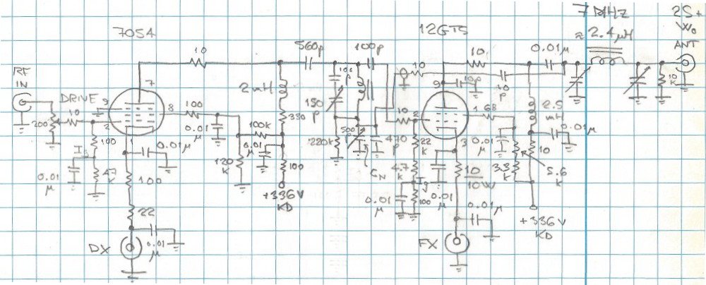
|
| Figure 9—Schematic diagram of a two-stage driver-amplifier strip capable of 20 to 25 watts output. As shown, low-impedance drive (50 to 200 Ω) is assumed; the 7054's 47 kΩ- and 100-Ω ohm resistors are transposed (100 Ω grounded) for high- or switchable-Z input. (A bypassed 100-Ω resistor in the grid returns of the driver and power amplifier allows the straightforward measurement of grid current with a VOM or DMM; each 0.1 V in 100 Ω is equivalent to 1 mA of grid current.) When the driver is reconfigured for high-Z drive, a 10- or 25-kΩ variable resistor in its cathode line can serve as a DRIVE control. Multiple beam power tubes have been successfully used in this circuit at various output powers with appropriate changes in output network, heater supply and power-amplifier screen voltage; these include television horizontal-amplifier tubes (6GY5, 12GT5, 17JT6A, 21HJ5, 21HB5A), vertical-amplifier tubes (6JB5, 6JQ6, 12JQ6), pulse regulators (17KV6A, 22KV6A), and the intended-for-class-C-RF-use 8156 and 7894. Do not omit the intrinsic-negative-resistance-parasitic-oscillation stopper resistance (shown as 68 Ω, but values from 47 to 100 Ω will suffice) in the power-amplifier screen! |
Fundamental crystals are used in all of the oscillator circuits described above; suitable HC-49 crystals are available for all the ham bands from 160 through 10 meters. Vintage crystals can be used as always.
| Revised February 5, 02022 CE. | Copyright ©2021 by David Newkirk (DavidNewkirk@gmail.com). All rights reserved. |
| home |