The Yaesu FR-101 receiver (manufactured from 1974 to 1978 CE, per the Radiomuseum) is an all-solid-state shortwave receiver that covers pre-WARC-1979 MF/HF amateur radio bands (160 through 10 meters, excluding 30, 17, and 12 meters) and a limited number of additional 500-kHz-wide bands between 1.5 and 30 MHz. The FR-101 accomplishes this with a double-conversion scheme that translates incoming signals to a tunable first intermediate frequency (IF) of 5520 to 6020 kHz, and then to a fixed second IF (3180 kHz) by means of an LC tunable variable frequency oscillator (VFO) that covers 8700 to 9200 kHz.
For $99 plus shipping I came to own an FR-101S—"for parts or repair"—that had been long-term immersed in water such that paint on the left end of its cabinet had been replaced by rust. I reasoned that at least I'd get a hundred-dollar look at a receiver that had intrigued me in the mid-1970s (while remaining unattainable because of its price), and if its main tuning and bandswitching subsystems were workable, I'd be able to repair or rebuild whatever else might be wrong, even if "rebuild" might have to mean settling for a radio that worked on only one or a few bands. This page chronicles my investigations, repairs, and modifications toward that rescue.
Session 1. I unpack the FR-101, remove its covers, and try its controls. On the water-damaged end, the AGC switch is movable but sluggish, and the SELECT switch (which controls whether VFO, crystal [fixed], or external frequency control is used) is frozen at INT—the right position, if it must be frozen, because INT is the setting that routes the FR-101's VFO to its second mixer for normal operation. But most of the set, even including the IF board (the board closest to the rusty end of the cabinet, and the board behind the AGC and SELECT switches edgewise) looks untouched by water—most importantly, the VFO and preselector parts, the workability of which would be necessary to get the radio working at all.
Session 2. Again removing the set's bottom cover for a closer inspection of the under-chassis parts, I see no water damage below, even on the rusty-cabinet end of the set. Interestingly, the bypass capacitor across the MUTE jack is fractured—especially interesting because I have been hoping that the set's "does not receive"ness might be caused by absence of a shorting plug in MUTE jack. Because an ac-line cord was not included with the set, I determine how to power the set from dc by means of its four-pin rear-panel Jones POWER connector. The set's push-on, push-off POWER switch doesn't spring-return to OFF freely, but I'm able to turn the set on and off by pushing and pulling the switch. Its dial, S meter, and VFO lights light. Plugging in headphones, I can hear the AF power amp's residual hiss; the hiss increases as I turn the control from minimum to maximum—a good sign! But there's no hiss increase when I turn up the RF gain. Most importantly, however, with my RF-2200 portable receiver I can hear the FR-101's VFO (8700–9200 kHz) and its crystal-controlled first-conversion oscillator for 40 meters (13.02 MHz)! The set's BFO—which operates at one of three frequencies around 3180 kHz—is inoperative.
Session 3. With my digital multimeter I determine that there's 6.06 volts on the FR-101's REG 6 V line, so the 6-volt regulator circuit is working and adjusted to spec. By repeatedly cycling and jiggling the MODE switch across its BFO-dependent positions (USB, LSB, RTTY, CW, CW-N) I succeed in bringing the set's BFO to life in the LSB position! Further fiddling makes the USB, CW and RTTY BFO channels come to life, if I position the MODE switch just so. Hoping that with the BFO operating I might now be able to hear a signal sweeping across the set's 3180-kHz IF, I straddle my old Panasonic RF-2200 AM/SW/FM portable receiver across the FR-101's open cabinet bottom such that the 2200's tuning capacitor—which quite conveniently is in the set's extremely lower right corner, with the 2200 viewed from the front—is close to the FR-101's IF-board connector. Assuming that the RF-2200 uses an intermediate frequency (IF) of 455 kHz during mediumwave reception, tuning 2200 through 1135 kHz should tuning the set's local oscillator (LO) through 1590 kHz, the second harmonic of which should be audible at 3180 kHz. But nothing heard.
Session 4. I determine that—apparently as a result of the fractured MUTE line bypass capacitor—the FR-101's MUTE line is hard-shorted to ground, keeping the receiver unmuted unless I press the STANDBY button (the successfully operation of which proves that that button, and the set's mute-ability, work). I measure 8.45 V on the set's AGC line at maximum RF gain. With the help of the RF-2200, I determine that the FR-101's crystal calibrator works. Examining the back of the RF ATTEN switch for the first time, I notice that at least one of the set's RF attenuator resistors is burned; perhaps someone transmitted into the 101's front end...
Session 5. Coupling an antenna to the input of the FR-101's crystal filters, with the set's BFO enabled—careful jiggling of the control is necessary—I can hear band noise at 3180 kHz! Tuning the RF-2200 through 1135 kHz with the 2200 close to the antenna lead reveals no swish across the IF, so I guess I'm mis-remembering the RF-2200's conversion scheme at the mediumwaves. Then I hold my tiny Sony SRF-59 AM/FM receiver, set to AM, near the antenna and tune it through 1135 kHz. There's the SRF-59 carrier swishing through the SSB filter! So now I've heard man-made signals at the FR-101's 3180-kHz IF!
Session 6. After some calculations of how signals at RF in a given band—say, 7000 to 7500 kHz—equate to frequencies in the FR-101's first-IF range—their sense reverses, mapping 7000–7500 to 6020–5520 kHz—I determine that a signal based on one of my 7120-kHz transmit crystals should be audible at 5.9 MHz. I try this by loosely coupling the Crystalizer (with 7120-kHz crystal) into the FR-101's front end and loosely coupling the RF-2200 to the output of the 101's three-stage, gang-tuned second-IF filter, but don't succeed in hearing the test signal get through to 5.9 MHz. (For all I know, poor contacts in the set's RF ATTEN and/or BAND switch might be making reception near-impossible.)
So I decide to try a related test: If I inject a signal somewhere in the 101's second-IF range into the input of the set's second mixer (MC1496G), might I be able to hear the test signal all the way out to audio? I've been assuming "no"—and assuming that the set's second mixer and related circuit were generally toast—on the basis of negative on-the-air-tuning-around results, but maybe a really strong test signal will give me a weak resultant I can start with as a basis for troubleshooting and alignment. I locate a 5750-kHz crystal in the junkbox, fire it up in the Crystalizer, loosely couple the 5750-kHz signal into the MC1496G's input, and tune...and there it is!
But it's really weak—weak, as in "something's really busted" weak. I decide to start troubleshooting this by removing and reseating the set's second-IF/noise-blanker board. I remove two hold-down screws, rock the board out, and...there's the problem: The set's optional 20-kHz-wide, 3180-kHz FM/noise-blanker-roofing filter (XF-30D) is absent and its INPUT and OUTPUT circuit-board pads are unjumpered!
I jumper the open "hot" filter terminals with a 0.1-μF capacitor. Now the test signal is much stronger, but band noise is still not as strong as I expect it should be. But wait: The circuitry at the XF-30D input is a parallel tuned circuit resonated by a capacitive voltage divider with 220 pF above and 2000 pF below, with the XF-30D driven from the junction of the divider capacitors. That implements high-to-low impedance conversion, so the XF-30D must have a low-impedance input (based on that capacitive division ratio) and a low-impedance output (terminated as it is by a 560-Ω resistor between the gate of a 2SK19 JFET and ground.) For now, I merely lift the grounded lead of the 2000-pF voltage-divider capacitor above common, turning the upper voltage-divider capacitor (220 pF) into a coupling capacitor. Eureka! With an antenna connected, I can now tune 40 meters with sensitivity well below the band noise! Additional tests at 80 meters (especially VOLMET at 3485 kHz), 31, and 25 meters succeed. Even the FR-101's AGC and S meter are operational, including the set's sluggish, water-damaged AGC switch, calming my concern that the S meter might have been waterlogged and destroyed. (Later, thanks to an Ebay photo of a for-sale FR-101 second-mixer/noise-blanker board, I learn that the INPUT and OUTPUT pads for the optional XF-30D filter are factory-bridged with a 25-pF ceramic capacitor, which official approach I then adopt after reconnecting the 2000-pF divider capacitor to common. After I've done this, the tuned circuit at the XF-30D input now exhibits a strong peak—which it didn't [as a result of heavy resistive loading by that 560-Ω resistor] with my slapdash 220-pF-divider-cap-as-coupling-cap workaround in place. A brickbat to Yaesu for not documenting XF-30D "with and without" in the FR-101S manual.)
All of a sudden, after only a few troubleshooting/repair sessions (and very little actual repair), I'm just generally tuning my favorite ham and shortwave broadcast bands with a "for repair or parts" FR-101S!
What issues are up for repair/modification? Aside from the obvious—contact-iffy switches that require careful juggling for positive contact, burned resistor or three in the set's RF attenuators—the set's audio is distorted ahead of the AF gain control in all modes. Central for me is the fact that the FR-101's keyed-pass-transistor-based AGC system design is, for want of a more-technical term, wacky: The high resistances in series with all of its timing capacitors, and the high capacitance across its AGC bus, guarantee that the set's AGC response cannot possibly exhibit the characteristics we've come to accept as standard even with AGC FAST set. I expect to fully redesign/rebuild the set's AGC system (done; used a subsystem from Hayward and DeMaw's Solid State Design for the Radio Amateur; full circuit to be described here as time allows) and AM and SSB detectors to solve this.
Secondarily, I may entirely do away with the set's noise-blanker circuitry—the close equivalent of which, in Kenwood's FR-101 competitor, the R-599, compromised the receiver's wideband blocking dynamic range—as another priority...unless the FR-101's way-cool triple-gang-tuned second-IF tracking filter disallows the blocking from far-off-channel signals that compelled me to bypass noise blanking in the R-599.
Lowering the FR-101's Receiving Pitch for CW and USB
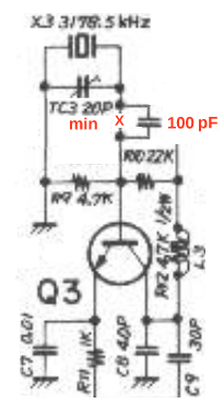
The FR-101's second intermediate frequency is 3180 kHz. With the receiver tuned to place incoming CW signals at exactly that frequency, the CW receiving pitch in a stock FR-101's is around 700 Hz—much higher than my preferred 400 to 500 Hz. To lower the pitch, the BFO signal provided by crystal X3 in conjunction with transistor Q3, nominally at 3178.5 kHz, must be moved closer to 3180 kHz. Setting TC3, the associated 20-pF trimmer capacitor, to minimum did not increase the BFO frequency enough. Sufficient frequency increase was achieved by installing a 100-pF capacitor in series with the parallel combination of X3 and TC3 as shown in Figure 1.
|
| Figure 1—FR-101 BFO subcircuit showing how to connect 100 pF in series with the paralleled combination of crystal X3 and trimmer capacitor TC3 to lower the receiver's CW receiving pitch. TC3 should be set at minimum capacitance when this is done. |
| Revised May 12, 02019 CE | Text not otherwise attributed is copyright © 2015–2019 by David Newkirk (DavidNewkirk@gmail.com). All rights reserved. |
| home |