The pi and pi-L networks commonly used to transform the impedance of antenna systems to values appropriate for loading vacuum-tube RF power amplifiers are peaked low-pass filters. If your transmitter's final amplifier uses one, minimizing subharmonic drive to the final grid is important because the output network will only modestly reject the subharmonic (Figure 1).
|
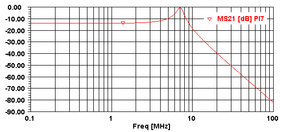
| Figure 1—Gain of a pi network that transforms 50 Ω to 5000 Ω at 7.05 MHz. The response at 3.525 MHz is down only 12 to 13 dB relative to the peak. (Analysis by ARRL Radio Designer, a circuit simulation software product now discontinued.) |
It should go without saying that using such a low-pass-filtered stage as a frequency multiplier is asking for trouble. True, the network won't be as efficient in transferring amplified subharmonic energy to the antenna system (which may not be capable of radiating subharmonic energy very efficiently), but in the interests of spectral purity and neighborliness, subharmonic transmitter output is something we should work to avoid, especially in designs where the driver doubles, as in a crystal oscillator that uses a 80-meter crystal to produce output at 40. This article presents a clever driver-output/final-grid circuit that can significantly reduce f/2 subharmonic energy applied to a transmitter's final amplifier.
Figure 2 shows the circuit, first described in print (so far as I know) by Warren Bruene, WØTTK (later W5OLY), on page 18–16 of the radio transmitters chapter he contributed to Keith Henney, ed. Radio Engineering Handbook, 5th ed. (New York: McGraw-Hill, 1959).
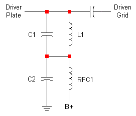 |
| Figure 2—The f/2-trap tank combines a parallel tuned circuit (L1C1) resonant at f and a series- tuned circuit L1C1-C2 resonant at f/2. |
L1 and C1 tune to the desired frequency f, where f is 2× the frequency present at the driver grid. At frequencies below resonance, L1C1 acts like an inductor. C2 series-resonates with L1C1's effective inductance at f/2, shunting energy at f/2 to common and significantly reducing its amplitude at the amplifier grid (Figure 3).
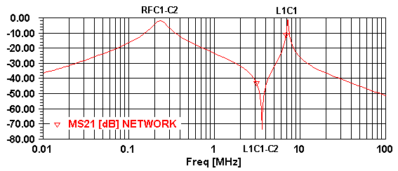 |
| Figure 3—Response of an f/2-trap tank circuit configured at 7 MHz for use with a 6AG7 driver and 6V6 final as simulated with ARRL Radio Designer. For this example, C1 = 156 pF (Q = 1000 at 7.9 MHz), C2 = 470 pF (Q = 1000 at 7.9 MHz), L1 = 3.14 μH (Q = 250 at 7.9 MHz), and RFC1 = 1 mH (Q = 35 at 252 kHz). Peaks occur at the parallel resonances of L1C1 and RFC1C2; L1C1-C2 contributes the dip. This analysis, produced with the circuit's input and output terminated with 10 kΩ, is intended to show the position and relative amplitude of the peaks and dip. In practice, their absolute amplitudes will depend on the particular L and C values used, their Qs, and the loading contributed by the driver plate and driven grid under operating conditions. |
If you can tune the circuit by varying L1 rather than C1, the two resonant frequencies will track. Even if you tune with C1, within a given band the f/2 notch should still give you more f/2 attenuation than the L1C1 tank would provide on its own (Figure 4).
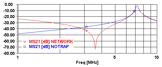 |
| Figure 4—Response of the 7-MHz tank with RFC1 and C2 present and absent showing the magnitude of f/2 rejection to be expected with the f/2-trap tank. A standard parallel-LC driver tank would probably be built to resonate at 7 MHz with considerably less capacitance than I've used in this f/2-trap tank example; such a tank would reject 3.5-MHz energy even less than the high-C L1C1 values used in this ARRL Radio Designer simulation. |
As a bonus, you can use the amplifier's grid-leak resistor in place of RFC1 (Figure 5, Figure 6).
 |
| Figure 5—(a) The driven stage's grid-leak resistor (R1) can replace RFC1 with little effect on the f/2 dip and f peak (Figure 6). For easy grid-current metering, put a 100-Ω resistor in series with R1's ground end and bypass it to ground with a 0.01-μF capacitor as shown at (b). You can then use a voltmeter to monitor the driven stage's drive (0.1 V across R2 = 1 mA of grid current). |
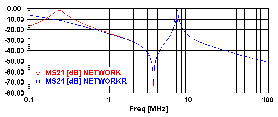 |
| Figure 6—Response of the 7-MHz tank with RFC1 versus the response with R1 = 18 kΩ. |
What values should you use for C1, C2 and L1? Engineering by the book would have us first determine L1C1 values that optimally load the driver tube. We'd then just multiply C1 by 1.5 to dimension C2. Because the driver is usually capable of significantly more output than the final drive needed, many builders, including me, will tend not to do so, dimensioning L1C1 using rules of thumb or calculations based on the characteristics of available parts. If, however, you'll be neutralizing your final amplifier tube—as I strongly recommend that you do—there's another, quite attractive option: The f/2-trap tank can mesh nicely with a widely used neutralizing circuit (Figure 7), with C2 serving as the neutralizing circuit's C.
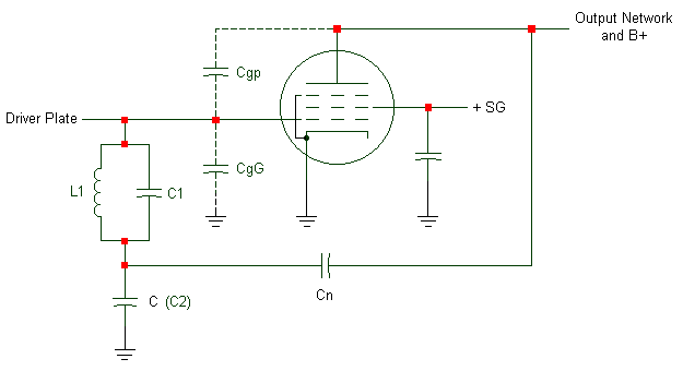 |
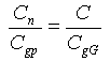
Figure 7—The capacitive-bridge neutralizing circuit described by Warren Breune in Warren Breune, "How to Neutralize Your Single-Ended Tetrode Final," April 1950, pages 11–nn, and later in Keith Henney, ed. Radio Engineering Handbook, 5th ed. (New York: McGraw-Hill, 1959) pages 18–28 to 18–29. Grid- and cathode-bias circuitry is not shown; several options are possible, including that shown in Figure 5. C, one of the neutralizing network's external voltage-divider capacitances, also serves as the grid tank ground return; Cn, the neutralizing capacitor, is the network's other external voltage-divider capacitance; Cgp is the driven tube's grid-plate capacitance; CgG represents all capacitance from the driven tube's grid to ground, including the driven tube's input capacitance, all "stray" capacitance to ground, and the driving tube's output capacitance (reduced by seriesing with any intervening coupling capacitances) if the driver and driven stages are capacitively coupled. The stage is neutralized when
|
With the f/2-trap tank and capacitive-bridge neutralizing circuits combined, you can determine usable values for the f/2-trap tank's C1, C2 and L1 by working backward from the neutralizing-circuit design:
The resulting L1C1 circuit will probably be higher-C than what you may be accustomed to seeing in a driver plate tank. Two modified behaviors may be noticeable during its use: The circuit will tune more sharply and may require repeaking a bit more often as you change frequency than a lower-C one, and the available final grid drive will likely be somewhat lower (at given driver plate and screen voltages) than that obtainable with more normally proportioned values of L1C1. If your driver tube is operating well within its capability—as it should be—modestly increasing its screen voltage should give you the drive you need.
| Revised December 1, 2016 CE. | Text and drawings copyright © 1998, 2007, 2016 by David Newkirk david.newkirk@gmail.com). All rights reserved. |
| home |