Crystals v Parallel L-C Tuned Circuits for Frequency Selection
Although we generally think of a quartz crystal as affording higher selectivity than a standard inductor-capacitor (L-C) tuned circuit, a crystal is not always the best choice when protection against far out-of-band signals is required. We'll explore why with the help of a software circuit simulator, Ansoft Serenade 8.5 SV.
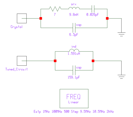
Figure 1 shows crystal-equivalent and L-C tuned circuits set up for simulation in Serenade 8.5 SV. At its fundamental (lowest-frequency) resonance, a crystal can be modeled as a series-connected small resistance (generally ohms to hundreds of ohms), large inductance (commonly on the order of millihenrys for high-frequency crystals), and very small capacitance (on the order of femtofarads to tens of femtofarads) connected in parallel with a small capacitance (on the order of a few picofarads). The series-connected elements simulate the crystal itself; the parallel capacitance simulates the capacitance formed by the crystal electrodes (one on each side of the crystal plate) with the crystal acting as a dielectric. In practice, such a network has two main resonances: a series (low-impedance) resonance formed by the crystal's seriesed equivalent resistance, inductance, and capacitance, and the parallel (high-impedance) resonance formed by the crystal electrode capacitance and the crystal (which at frequencies above its series resonance acts like an inductor, and below its series resonance point acts like a capacitor). A crystal's parallel resonance is always slightly higher in frequency than its series resonance, giving rise to a sharp-dip-and-sharp-peak impedance characteristic with rising frequency.
 |
|
Figure 1—Schematic diagram of the equivalent electrical circuit of the fundamental (lowest-frequency) resonance of a quartz crystal (Crystal) and of a parallel-resonant L-C tuned circuit (Tuned_Circuit) as entered for simulation in Ansoft Serenade 8.5 SV. Both circuits are dimensioned to resonate (series resonance for the crystal, parallel resonance for the L-C circuit) at 10 MHz. The L-C tuned circuit inductor has a Q (quality factor) of 200 at 10 MHz; its capacitor is lossless. Although all of the simulated crystal's reactive (inductive and capacitive) subelements are lossless, the presence of a nonzero series resistance (7 ohms) indirectly sets a realistic Q for the crystal.
|
|
|
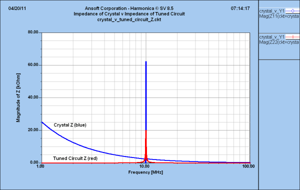
Figure 2—Predicted magnitude (absolute value) of impedance versus frequency for the crystal and parallel L-C circuits. The very low impedance of the parallel L-C circuit above and below resonance equates to significant rejection of off-resonance signals when such a tuned circuit is used as a signal selector.
|
 |
|
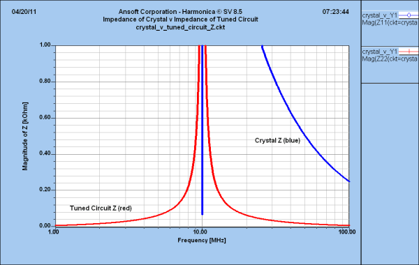
Figure 3—How low is low? This graph shows the predicted magnitude (absolute value) of impedance versus frequency for the crystal and parallel L-C circuits with the impedance axis scaled to 1 kilohm. Only in a very narrow region around its series resonance (blue downward spike) does the crystal's impedance equal the generally low off-resonance impedance exhibited by the parallel L-C circuit.
|
|
|
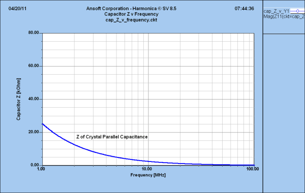
Figure 4—Predicted magnitude of impedance versus frequency for an ideal 6.3-pF capacitor, plotted on the impedance scale used in Figure 2. That this curve duplicates the off-resonance behavior of the simulated crystal indicates that the crystal's relatively high off-resonance impedance is almost entirely attributable to its small parallel (interelectrode) capacitance.
|