The current trend toward self-controlled and readily adjustable oscillators for amateur use, together with recent FCC rulings, makes it increasingly important that those oscillators be of the utmost stability. The purpose of this article is to describe a method of improving the stability of the ordinary electron-coupled oscillator.
The Conventional Circuit
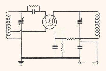
Consider Figure 1, which is a diagram of the conventional e.c.o. It will be observed that the control gird, screen grid, and cathode of the tube are connected in a Hartley circuit, with the screen has the anode but at ground potential for r.f. in order to obtain screening action. The electron stream to the plate is controlled by the oscillating portions of the tube in such a way that power at either the fundamental frequency or one of its harmonics may be obtained from the plate circuit.

|
| Figure 1—Conventional electron-coupled oscillator circuit. |
There are two reasons why this circuit is inherently more stable that the simple Hartley. First, changes of screen and plate voltage in the same direction and of the same percentage tend to cause opposite changes in frequency. Second, because of the screen action within the tube, there is presumably no coupling back from the plate circuit, or output circuit, to the grid-cathode-screen circuit, which determines the frequency, thus, changes in plate loadirng or tuning cannot affect the frequency.
The second point contains the joker, however, because in all but a few tubes, and particularly in those capable of delivering a reasonable amount of power, the grid-plate screening is not adequate at the higher frequencies. The result is severe interaction between plate loading and tuning and the grid circuit. This may, and often does, result in chirps or frequency modulation if the following stage is improperly neutralized and drives a keyed or modulated stage.
Neutralizing the Oscillator
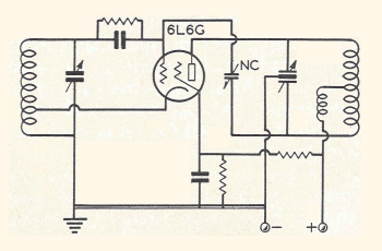
A method of obviating, or at least minimizing, the effect of insufficient screening is to neutralize the grid-plate capacity of the tube, exactly as in an r.f. amplifier. This may sound paradoxical, since neutralizing is commonly thought of as preventing oscillations, but remember that the plate in an e.c.o. is not a part of the oscillating circuit. Figure 2 shows such a neutralized oscillator; the neutralizing scheme is conventional every respect. Since operation over a wide range of frequencies and several bands may be required, the use of a split-stator tank condenser is advised. With this, the neutralizing adjustment need be made only once. One thing--with this system of neutralizing, the center tap of the coil should never be bypassed to ground, but should be fed through an r.f. choke.

|
| Figure 2—Electron-coupled oscillator circuit using a 6L6G with neutralizing circuit added. |
In tests using this circuit with a 6L6G, the reaction on the fundamental frequency was so great without neutralization that at certain settings of the plate condenser oscillation was stopped altogther. With the oscillator neutralized, however, the stability compared very favorably with that of a 24A which was doubling; the output, of course, was very much greater with the 6L6G.
The need for good shielding, solid mechanical construction, and well-regulated power source is, of course, as great for this circuit as for any oscillator; time spent on these matters will be well repaid.
| Clifford E. Berry, W9TIJ, Radio, November 1939 CE, pages 50 and 86. Berry was the co-creator of the Altansoff-Berry Computer (http://en.wikipedia.org/wiki/Atanasoff%E2%80%93Berry_computer). | Page revised September 3, 2014 CE. |
| home |